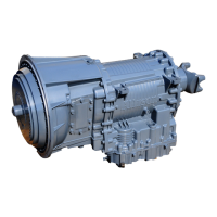
10.2PLANETARYGEARSANDCLUTCHES
Aseriesofthreehelical,constantmeshplanetarygearsetsandshafts
providesthemechanicalgearratiosanddirectionoftravelforthevehicle.The
planetarygearsetsarecontrolledbyvemulti-plateclutchesthatworkinpairs
toproduceuptosixforwardspeedsandonereversespeed.Theclutchesare
appliedandreleasedhydraulicallyinresponsetoelectronicsignalsfromthe
TransmissionControlModule(TCM)totheappropriatesolenoids.
10.3COOLERCIRCUIT
Thetransmissionuidiscooledbyanintegral(transmission-mounted)or
remote-mountedoilcooler.Connectionstothecoolingcircuitarelocatedat
thefrontorrearofthetransmissiontofacilitateinstallationofremotecooler
lines.Onretardermodels,onlytherearcoolerportsmaybeused.Theintegral
coolerismountedonthelowerrearportionofthetransmission,replacingthe
remotecoolermanifold.Integralcooleroilportsareinternalrequiringcoolant
toberoutedtoandfromthecooler.
10.4RETARDER
Theself-containedretarderisattheoutputofthetransmissionandconsists
ofavanedrotorwhichrotatesinavanedcavity.Therotorissplinedtoand
drivenbytheoutputshaft.Whentheretarderisactivated,theuidinthe
accumulatorisdisplacedintotheretardercavity.Thepressurizeduidinthe
cavityactingagainsttherotatingandstationaryvanescausestheretarder
rotorandoutputshafttoreducespeed,slowingthevehicleorlimitingspeed
onadownhillgrade(referto4.3USINGTHEHYDRAULICRETARDER)for
additionalinformation.Whentheretarderisdeactivated,theretardercavityis
evacuatedandtheaccumulatorisrechargedwithuid.
Theretarderhousingalsoallowstheadditionofeitheraremoteorintegral
coolerfortransmissionsumpuidinadditiontoretarderoutuid.Abypass
coverisplacedoverthesumpcoolingportswhentheprovisionisnotused.
Thesumpcoolerportsarelocatedonthelowerrightrearfaceoftheretarder
housing.RefertoFigure2–1,Figure2–2,andFigure2–5,Figure2–6.
10.5CONTROLVALVEMODULE
The3000and4000SeriesTransmissioncontrolvalvemoduleisboltedtothe
transmissionmainhousing,andcontainthemainandlubelters.Thecontrol
valvemodulealsocontainsamainvalvebodyassemblyandsolenoidvalve
bodyassembly.TheTransmissionControlModule(TCM)issuescommands
thatactuatetherangeclutchsolenoidstogovernuidowtothecommanded
rangeclutchesandlockupclutchcontainedinthetorqueconverter.
148

 Loading...


