ENG
12 / 32 6-1624870 rev. 2 23/06/2020
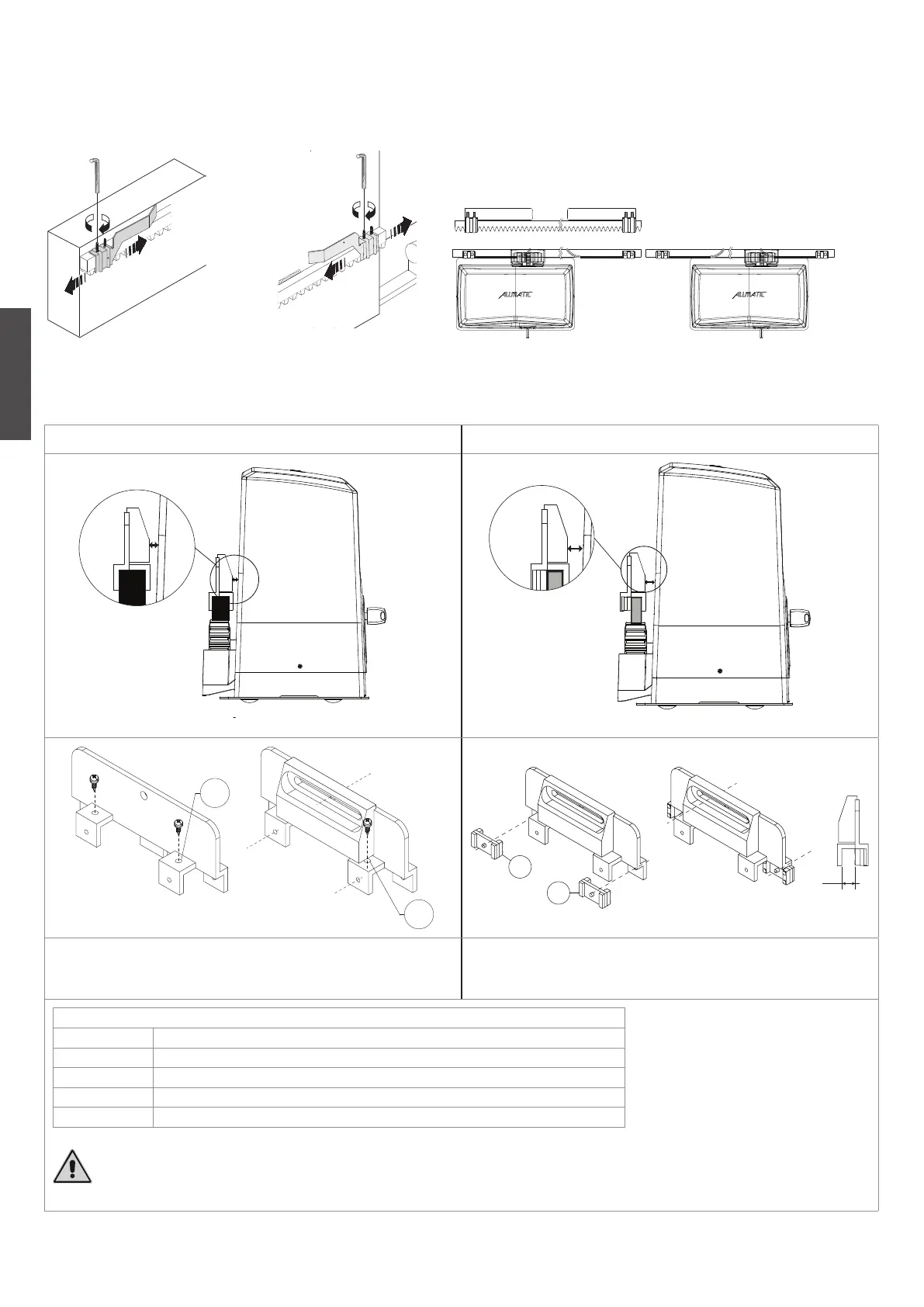
LIMIT SWITCH FITTING
In order to determine the gate travel length, place two cams (Fig. 9) at the ends of the rack (Fig. 10). Move the cams on the rack teeth to adjust their
opening and closing travel. To fix the cams to the rack, tighten the screws issued.
Note: In addition to the electric stop cams mentioned above, you must also install strong mechanical stops preventing the gate from sliding out from the
top guides.
Fig. 9
DXSX
Fig. 10
INSTALLATION AND REGULATION OF MAGNETIC HALL LIMIT SWITCHES. Only for versions with magnetic limit switches
Rack 28 x 20 / 6410001 (nylon with steel core) Rack 30 x 12 / 6410005 (galvanized steel)
40 mm MAX
Fig. 11
40 mm MAX
Fig. 12
A
A
12
B
B
NOTE: If necessary make 2 additional holes to improve the fixing (A) and copy
them on the rack. Pay attention to the screws choice, they mustn’t be too long
and obstruct the grip.
If you use the steel rack type 30 x 12 (CODE 64100005) use the supplied
spacers and position them as shown in the figure to respect the distance
indicated.
Magnetic limit swithces connection
+ 24Vdc White
- GND Brown
COM Yellow
L.S.1 Green
L.S.2 Grey
WARNING! There must be a maximum distance of 40 mm between the magnet attached to the rack and the sensor on the
body of the motor. (Fig. 11, Fig. 12)
 Loading...