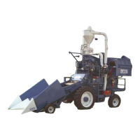
The ALMACO SPC 20 Combine is a self-propelled agricultural machine designed for harvesting various crops. It functions as a "laboratory instrument" capable of volume production while meeting the rigid requirements for field trials and evaluations. The combine is virtually hand-assembled by skilled craftsmen from durable, premium-grade materials to rigid production standards.
Function Description
The threshing operation is accomplished by a hydraulically driven, 15-1/4" diameter, variable speed rasp bar cylinder and one adjustable, underslung, grated style concave. A strawpuller is positioned directly behind the threshing cylinder, which prevents cylinder wrapping and assists the movement of plant material through the machine. An adjustable/removable curtain is also utilized to prevent seed rebounding and to control threshed material flow.
Threshed material falls upon the first mechanically driven sieve where seed and smaller material fall through the sieve onto an upper internal conveyor. The conveyor carries separated material to a finer mesh lower sieve. The second sieve traps smaller material and allows the seed to fall through onto a lower internal conveyor. This conveyor drops the seed into the winnowing blower air stream. The large winnowing blower located at the lower portion of the machine directs an adjustable air stream across the discharge area of the lower sieve and conveyor. In this secondary cleaning stage, the remaining debris in the seed sample is discharged out the rear of the machine. Seed falls through the winnowing blower air stream and into the venturi tube and cyclone air stream. The cyclone blower air stream lifts seed through the venturi tubes to the cyclone seed hopper. Several different options direct the seed to a number of different locations.
After grain is harvested, it can be directed to a bulk grain tank using a Y-valve for bulk harvesting and seed increase. Shifting the Y-valve can divert samples to a bagging station either next to the driver or to a side bagging station. These stations are equipped with weigh hoppers and moisture probes to facilitate in-field data capture. Hydraulic unload auger options allow easy unloading of grain tank, and hydraulic dump hopper options allow simple unloading of bagged samples.
The combine is designed for feeding, threshing, separating, and cleaning operations. These operations are interrelated to produce a good overall harvesting result. Because of these relationships, the proper adjustment to fix a problem may not be obvious. Adjustments must be made quickly and correctly to allow efficient harvesting.
Important Technical Specifications
- Fluid and Capacities:
- Engine Oil: 15W-40 class CC/SE or CD/SE
- Hydraulic Oil: Dexron II or compatible
- Fuel: Diesel (sulfur content less than 5%)
- Engine Tank Capacity (w/filter): 7.5 qt
- Hydraulic Tank Capacity: 15 gal
- Fuel Tank Capacity: 25 gallon
- Shaft Speeds:
- Engine: Preset at factory
- Jack Shaft: 725-750 RPM
- Shaker: 190-220 RPM
- Cyclone Blower Shaft: 3000 - 3500 RPM
- Threshing Cylinder Shaft: 0-1000 RPM
- Strawpuller: 215 RPM
- Internal Conveyor: 200 RPM
- Winnowing Blower Shaft: 1000-1600 RPM
- Engine:
- Mfg/Typ: Duetz TD2011L04i EPA Tier 3
- 4 cyl. Turbo-charged air-cooled diesel
- Max. Torque: 177 lb-ft (240Nm) @ 1700 RPM
- Max. Output: 72 hp (54kW) @ 2600 RPM
- Ground Drive:
- Forward/Reverse: Hydrostatic
- Ground Speed: 0-6 mph
- Options: Rear Wheel Assist
- Tires:
- Front: 11.2-24 6ply
- Rear: 8.5L-14 6ply
- Options may modify tire sizes
- Threshing Cylinder:
- Type: Closed metal rasp bar
- Speed: 0-850 (0-1250 opt)
- Width: 31.5"
- Diameter: 15.25"
- Number of Bars: 8
- Control: Hydraulic
- Concave:
- Style: Under-slung Open Grate
- Adjustment: Worm Gear Driven, Rear Hinged
- Shaker Pan / Sieves:
- Stroke Length: 3"
- Opening Size (mm): 6,8,10,14,16,18,20,22,32
- Upper Sieve Dimensions: 30" x 55"
- Lower Sieve Dimensions: 30" x 47.5"
- Sieve type: Aluminum Graepel
- Upper Sieve Area: 1650 in²
- Lower Sieve Area: 1425 in²
- Strawpuller:
- Diameter: 8"
- Speed: 215 RPM
- Winnowing Blower:
- Type: Forward Curved Radial Impeller
- Volume Control: Shutter Door
- Diameter: 10-5/8" (27cm)
- Speed Control: Variable Pitch Sheave
- Cyclone Blower:
- Type: Centrifugal Fan
- Diameter: 13.5" (34.29 cm)
- Air Speed: 7350 - 9050 fpm
- Speed Control: Variable Pitch Sheave
- Electrical:
- Charging System: 55A alternator
- Battery: 12V negative ground
- Dimensions:
- A: Wheel Base: 6'-4"
- B: Base Machine: 10'-2"
- C: Machine w/ header: 17' 6"
- Width: 7' (Not Shown) (Options Can Modify Width)
- D: Height: 7'-6"
- E: Ground Clearance: 11"
- Machine Gross Weight: 5500lbs (Options will modify weight)
- Standard Head Weight: 1800lbs
- Row Crop Head Weight: 2600lbs
- Corn Head Weight: 2400lbs
Usage Features
The operator's control panel includes:
- Engine Throttle: Pushing forward increases engine rpm, pulling backward decreases engine rpm. Engine must be run at maximum rpm when operating. Do not drive machine at idle, reduced charge pressure will ruin brakes. Maximum engine rpm is set at factory and should not be modified.
- Switch Panel: Contains a number of switches and fuses, which control and operate standard controls and individual options. The orange Brake Switch enables the parking brake, use parking brake whenever machine is not moving. Parking brake automatically engages when the engine is shut off. Brake switch must be on before engine will start. The yellow Clutch Switch located here enables the electric clutch, engage the clutch only at idle RPM to avoid damaging clutch. Clutch switch must be off before engine will start. Optional auger switches with yellow boots must also be in the off position before the engine will start.
- Ignition Switch: Turn one click counter-clockwise for accessory power, one click clockwise to turn machine power on, full right and hold to start engine. For engines with cold-starting aid (heating plug) refer to engine operation in engine manual.
- Engine Oil Pressure: Displays engine oil pressure in psi. Normal operating oil pressure is 30 – 60 psi.
- Tachometer: Displays the digital tachometer is the current speed of the threshing cylinder in revolutions per minute (rpm). See Cylinder / Concave Setting chart in this section for approximate cylinder speed according to crop. Some adjustment may need to be made to cylinder speed to adjust for field and crop conditions.
- Forward / Reverse Hand Control: This lever controls the hydraulic fluid flow to the drive wheels. Push the lever forward to drive the machine forward, pull the lever back to drive the machine in reverse. Move the lever slowly and steadily to avoid machine bucking or jerking. Center the handle to return the machine to neutral. If the machine will not turn over, be sure that this lever is in the neutral (centered) position. The neutral safety switch will disable the ignition switch until the hand control lever is returned to the center position.
- Threshing Cylinder Speed: Threshing cylinder speed is a cable controlled hydraulic drive. Change cylinder speed only when combine is running and clutch is engaged. See the Cylinder / Concave Settings Chart for approximate speed according to crop. Some adjustment may need to be made to cylinder speed according to field and crop conditions.
- Ground Speed Control: Push foot control stop handle down to engage the foot control stop. When stop is set it can be used to quickly reach operating ground speed and keep a consistent speed through plots. Pull handle up and turn to lock in the disengaged position.
- Header Speed: The speed of the rotating knives, gathering belts, snapping rollers, drag chains, and/or reel speed. Header speed must be set to match, or slightly slower than the ground speed. Header speed is controlled by a Racine valve, which adjusts hydraulic oil from the threshing cylinder drive. When adjusting the header speed it is necessary to adjust the threshing cylinder rpm to compensate for hydraulic flow adjustment.
- Header Lift: This lever raises the head to avoid rocks, holes, and other obstacles. When clear of obstacles the header height lever should be pushed forward to allow the head to ride on the header gauge wheels. It is important to lift the head whenever turning around or at road speed.
- Reel Lift (Optional): Pull back on this lever to raise the reel. Push forward on lever to return reel to preset gauge arms.
- Folding Unload Auger (Optional): This lever controls a hydraulic cylinder, which controls the top portion of the folding unload auger. Push forward and hold the lever to actuate the cylinder until the auger is in the unload position. Pull back on the lever to lower the auger to legal transport height.
- Reverse Foot Pedal: Returns forward reverse lever to neutral position.
- Forward Foot Pedal: When the speed control lever is set the forward foot control can be used to quickly move the machine up to harvesting speed, allowing the operator's hands to be free for other operations. Depress foot pedals slowly and consistently to avoid machine bucking and jerking.
- Cylinder / Concave Clearance Adjuster: Cylinder / Concave Clearance is a critical aspect to produce proper threshing action without suffering seed damage. Rotate the adjuster clockwise to increase clearance and counter clockwise to decrease clearance. Tighten set bolt to lock concave in position.
- Fuel Gauge: Displays fuel level. Add diesel fuel only.
- Voltmeter: Displays voltage supplied by the main power alternator. The voltmeter should read between 13.5 - 14.5V at full engine rpm. Check this gauge if electronics act sluggish, or if there are electronics problems in general. If voltage drops or rises outside of the 13 - 15V range diagnose the problem.
- Engine Oil Temp: Displays the engine oil temperature in psi. Normal operating oil temperature is 266°F (130°C) the engine will be shutdown. When this happens it is necessary to allow the engine to cool down to a safe operating temperature. Before restarting check engine oil levels, remove excess debris from oil cooler, engine fan, and engine.
- Hour Meter: Shows the number of hours the machine has been in operation. It is important to keep track of hours to follow proper maintenance.
- Charge Pressure: Charge pressure must maintain a pressure of 200-350 psi. Check this gauge if hydraulic functions do not seem to be responding.
Maintenance Features
The manual provides a comprehensive maintenance schedule and guidelines for ensuring the longevity and optimal performance of the combine.
Maintenance Schedule (in hours of operation):
- Combine:
- Check all chain drives for proper tension, sprocket wear, and lube: X (Required service interval)
- Check all belt drives for wear and proper tension: X
- Check for oil and hydraulic fluid leaks: X
- Grease header pivots: X
- Check linkages for proper operation: A (Annually or at hour interval which ever comes first)
- Check rubber shaker bushings condition and alignment: A
- Check impellers for loose fins and clean: A
- Front and Rear Axle:
- Lubricate rear axle pivot, spindles, tie rods: X
- Check front and rear tire pressure (See side walls): A
- Retorque all wheel bolts and lug nuts: I (Initially, at hour interval thereafter)
- Change torque hub oil (90 wt.): B (Biennially (every two years) or at hour interval)
- Engine:
- Clean oil cooler cooling fins: X
- Change engine oil and oil filter: I, A
- Clean battery cables, posts, and cable ends: A
- Replace fuel filter: I, A
- Clean fuel pre-filter: B
- Hydraulic System:
- Change hydraulic oil filters: A
- Change hydraulic oil: B
- Header (Row Crop & Standard Head):
- Check for excessive wear on all components: X
- Lube gauge wheel pivots: A
- Check gauge wheel tire pressure (See tire sidewall): A
- Repack gauge wheel bearings: A
- Check conveyor belts tension, tracking, and lacing: X
Daily Maintenance Checklist:
- Check safety equipment.
- Lubricate cyclone bearings, 1 pump only.
- Lubricate winnowing blower bearings, 1 pump only.
- Check air filter indicator, clean filter if required.
- Check engine oil level, check for leaks.
- Check hydraulic oil level, check for leaks.
- Remove plant material from head and combine.
High Pressure Washing:
High pressure cleaning with water and mild solvent is advisable.
- Begin wash down by flooding entire machine with solution. This assists in floating abrasive particles off the machine, which might otherwise be blown into bearings and other critical surfaces as the cleaning procedure continues. A safe distance of 2 to 3 feet between nozzle and machine is recommended.
- Avoid close contact of nozzle to machine (less than 12" to 15"), as high pressure jet stream at this distance imparts a cutting action which could lift and remove paint where worn or broken spots in paint occur. In addition, close nozzle contact may also blow grease from bearings and other lubricated surfaces, leaving exposed parts susceptible to rusting.
- Lubricate all bearings and other lubricated surfaces after washing and run machine for a short period to aid in moisture removal.
- Engine may be washed totally, but avoid trapping moisture in electrical components, and do not wash a "hot" engine with cold water, as the differential in temperature could cause cracking of exhaust manifold and other cast components.
- Mild solvents of a non-flammable nature may be suitable for cleaning, provided manufacturer's specs are compatible with alkyd enamels, rubber and plastics as used on the self-propelled combine units.
- Using steam as a cleaning agent is not recommended by ALMACO, as steam is viewed as a potentially destructive agent to plastics, paint and rubber and promotes rust and corrosion of components, which are not immediately protected after cleaning.