SPC 20 OPERATOR’S MANUAL
STORAGE AND TRANSPORTATION F-3
STORAGE AND TRANSPORTATION
RECEIVING THE COMBINE
Each ALMACO SPC 20 combine is shipped tested. All field adjustments need to be made prior to
field use. See the Initial Cylinder / Concave Settings Chart for the crop being harvested. The
TROUBLE SHOOTING SECTION will also help in setting up your combine. Crated units are
shipped partially dismantled, with fuel tank and crankcase empty. The battery is also disconnected.
Be sure to fill crankcase with 15W-40 oil before starting engine. Fill hydraulic reservoir with Dexron II
or compatible automatic transmission fluid before starting engine. To assist in reassembling each
part removed is shipped with individual identity tag and/or special instructions if required. Make use
of the drawings and/or photos supplied to facilitate reassembling. Employ proper care and sound
mechanical practice in the tightening sequence of all bolts, wheel lugs and any other part removed
for shipment.
CAUTION!
Each intended operator should be completely familiar with the full range of operations
and field adjustment procedures prior to actual start up.
TRANSPORTING THE COMBINE
For reasons of safety and mobility, a suitable trailer meeting the requirements below should be
provided if distance from storage point to field site is considerable.
Length (base machine): 11’ 9” (3.6 m)
Length with Head: 19’ 6” (5.9 m)
Width: 7’6” (2.3m)
Height: 10’ 6” (3.2 m)
Ground Clearance: 11” (28 cm)
Gross Weight: 7,200 lbs. (4500kg)
LOADING / UNLOADING PROCEDURE:
1. With ramps down and trailer secured, lift header to obtain proper clearance.
2. Slowly drive combine forward onto trailer. Some machines will need to be backed on because of
head and/or trailer configurations. Exercise caution to avoid injury to operator or damage to
machine.
3. Position machine for proper weight distribution.
4. Lower header and engage parking brake.
5. Tape exhaust closed to prevent damage to turbocharger.
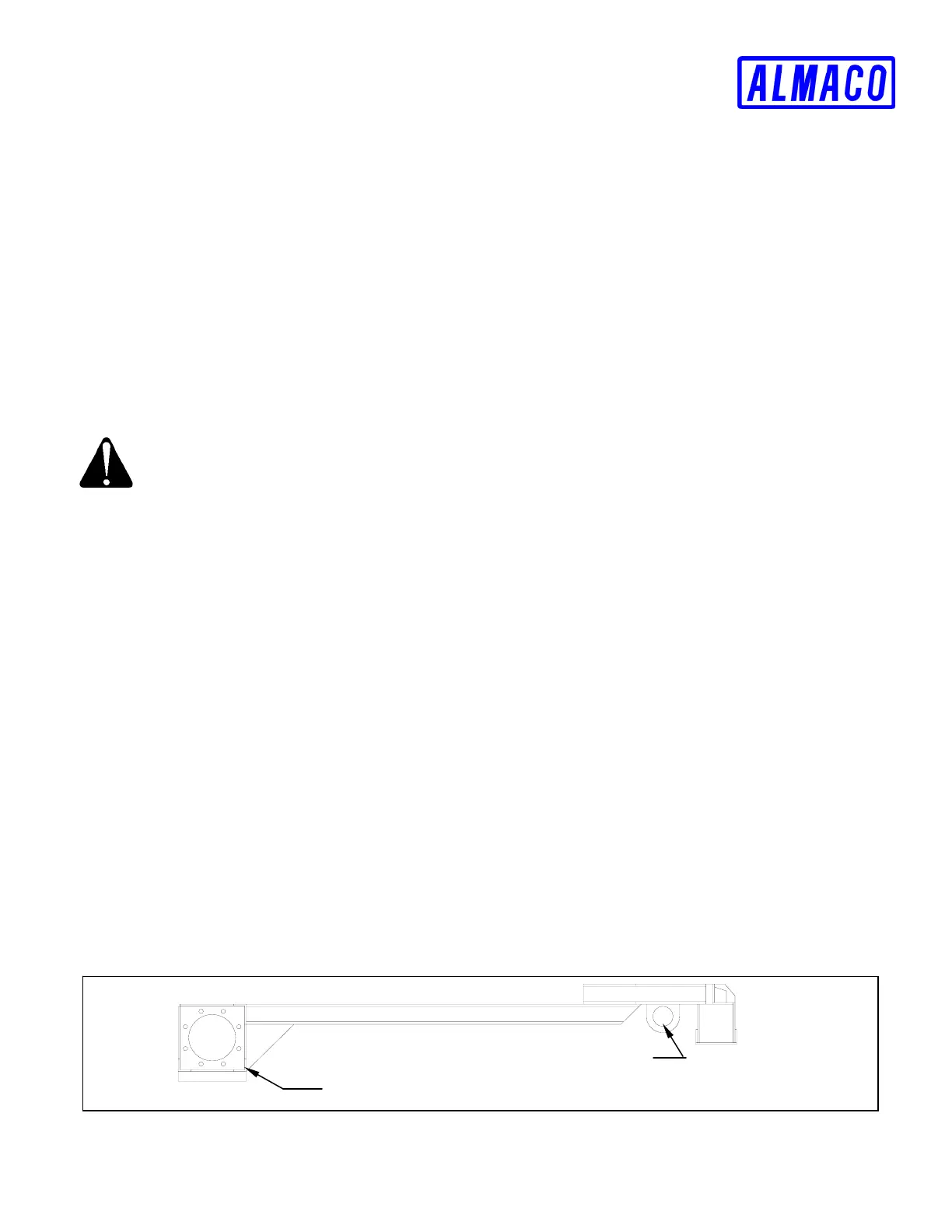
6. Secure machine to trailer firmly using tie downs (as shown on FIGURE F-1).
FIGURE F-1 Tie Down Locations
LOOP CHAIN THROUGH AXLE
LOOP CHAIN THROUGH
CHAIN TIE DOWN