System shall be turned on in the correct sequence to avoid any damage.
System shall be turned off in the correct sequence to avoid any damage.
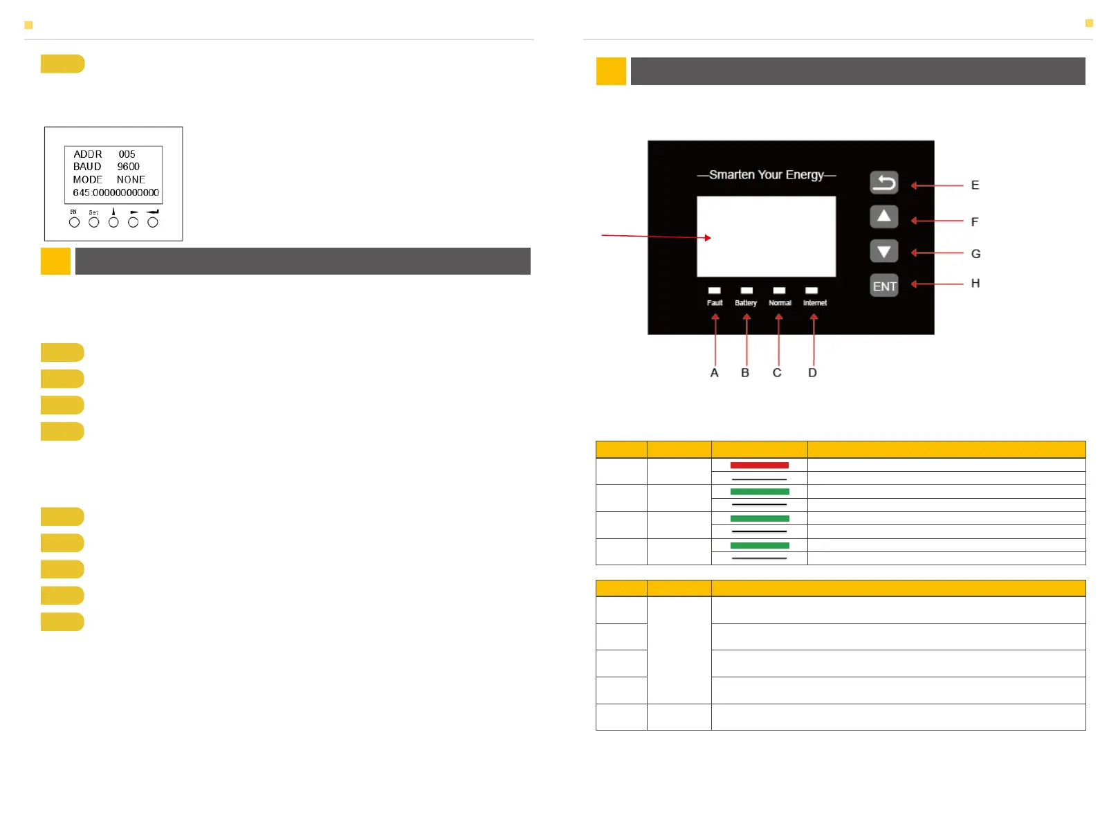
Figure 42 SMILE-T10 EMS Interface
3.1 Switch On
3.2 Switch Off
4.1 Function Description
Step 1 Turn on the MCCB and the AC switch of HV50056 shows.
Step 2 Turn on the external On-grid AC breaker
Step 3 Turn on the PV switch (DE: PV switch on inverter; AU: external PV switch)
Step 4 If backup load is applied, turn on the external Backup AC breaker
Step 5 Set the communication address and communication baud rate in the commu-
nication setting interface. When the meter is used as the Grid meter (DC, AC/Hybrid
system), the address is set to “005”. When it is used as the PV meter (AC/Hybrid
system), the address is set to “006”. The baud rate is set to 9600;
Step 1 Remove the front panel of the inverter and HV50056
Step 2 If backup load is applied, turn off the Backup AC breaker.
Step 3 Turn off the MCCB of HV50056 and the ac switch on HV50056
Step 4 Turn off the PV switch (DE: PV switch on inverter; AU: external PV switch)
Step 5 Turn off the On-grid AC breaker.
EMS INTRODUCTION AND SET UP04
SYSTEM OPERATION03
ON: Fault
OFF: No Fault
ON: Battery communication is OK
OFF: Battery communication is lost
ON: System works normally
OFF: System is abnormal or warning
ON: System is communicating with server
OFF: System is not communicating with server
A
B
C
D
Fault
Battery
Normal
Internet
Return Button: Escape from current interface or function
Up button: Move cursor to upside or increase value.
Down Button: Move cursor to downside or decrease value.
ENT Button: Confirm the selection.
Display the information of the inverter in this LCD screen.
E
F
G
H
I
Button
Function
LCD Screen
SYSTEM OPERATION
Item
Name
Status Description
Object
Name
Description
EMS INTRODUCTION AND SET UP
I
31 32
 Loading...