1.4.1.2 LED Display
1.4.2 HV50056
1.4.2.1 Specifications
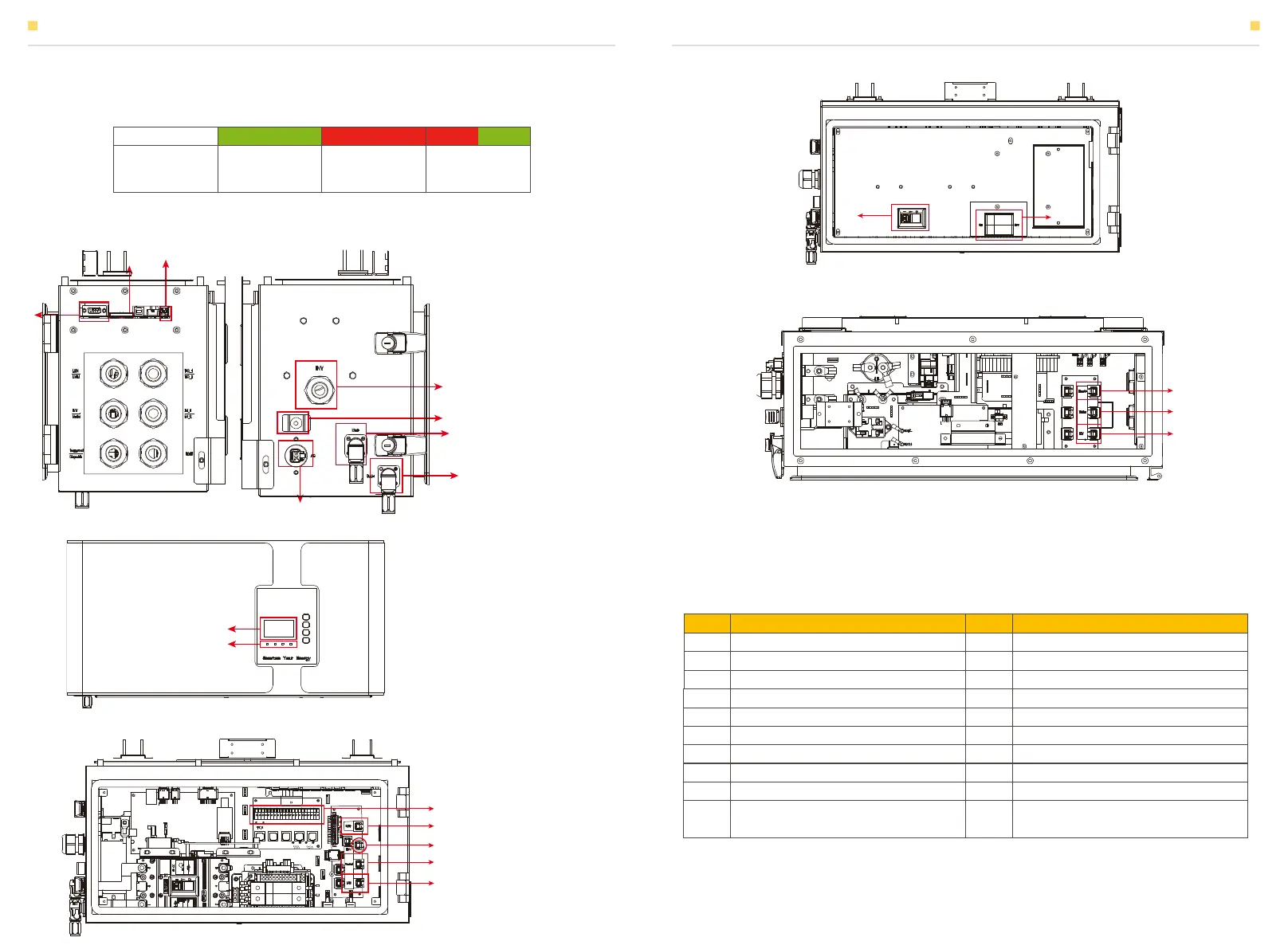
Figure 9 High-voltage Control Box – Front View, Inside
Figure 10 High-voltage Control Box – Top View
In normal condition, LED display three status:
INTRODUCTION
Figure 7 High-voltage Control Box – Left & Right View
Figure 8 High-voltage Control Box – Front View
1
3
2
12
10
9
14 15
18
19
20
11
13
16
4
5
6
7
8
17
Status Normal Protection Fault
LED Display
Green light
blinks for 1 sec
Red light
blinks for 1 sec
Red and green
lights blink for
1 sec
1
2
3
4
5
6
7
8
9
10
11
12
13
14
15
16
17
18
19
20
No. Description DescriptionNo.
External LCD Wiring Port
SD Card
Dip Switch
Dry Contact
LMU COM Port (CAN)
BMU COM Port (CAN)
COM Port Reserved
LAN COM Port
INV + / INV -
Earthing Point X 2 (Required to connect
with grounding copper)
AC Auxiliary Input
Bat+
Bat-
Molded Case Circuit Breaker (MCCB)
AC Switch (For AC Auxiliary Input)
LCD Screen
LED Indicator
External Dispatch COM Port
EMS Meter Communication Port
INV COM Port
INTRODUCTION
07 08