12
Subject to change without notice | 83053500oUK | ait-deutschland GmbH
5. Connect the device to the fixed piping of the heat-
ing circuit via vibration decouplings (accesso-
ry or included in the scope of delivery of the wall
duct or hydraulic connection line). You must install
them to prevent the transfer of structurally borne
sound to the fixed piping.
NOTE
If an existing system is being replaced, the
old vibration decoupling may not be reused.
Vibration decoupling installation instruction
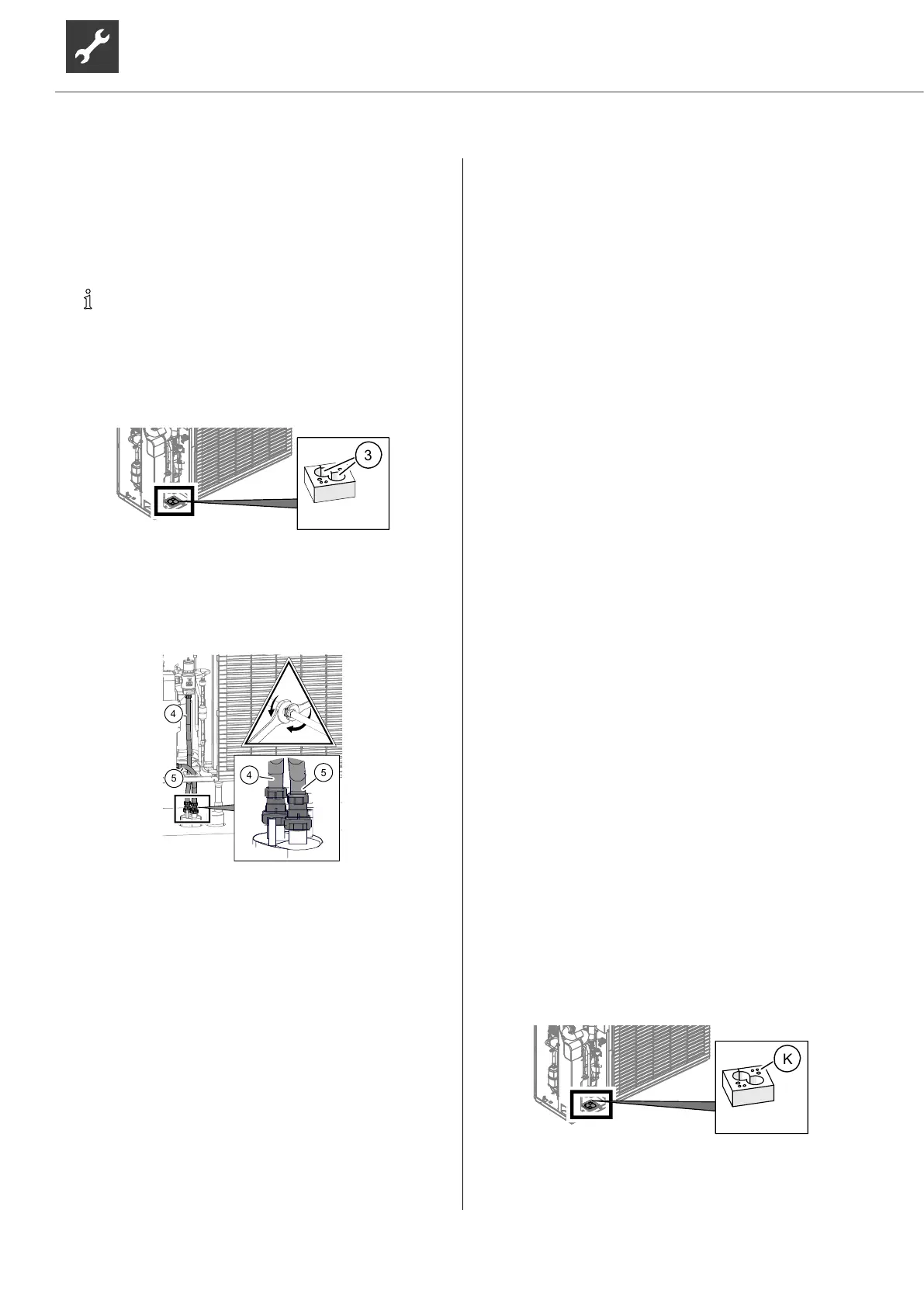
5.1. Route the vibration decouplings through the feed-
through (③) in the sealing plate.
5.2. Screw the vibration decouplings onto the two
pipes in the wall duct or hydraulic connection line.
Connect the flow line (④) first, then the return line
(⑤).
Example: hydraulic connection line
4 Heating water outlet (flow)
5 Heating water inlet (return)
6. If no further connection work is carried out after-
wards, mount the side facade and cover of the de-
vice.
6.3 Pressure safety
Equip the heating circuit with a safety valve and dia-
phragm expansion vessel in accordance with local
standards and guidelines.
Also install filling and draining devices, shut-off devic-
es and non-return valves in the heating circuit.
7 Electrical installation
7.1 Establishing the electrical
connections
IMPORTANT
Irreparable damage to the compressor due to wrong
rotating field
(only applies to units with 400V connec-
tion).
► Ensure a clockwise rotating field for the compres-
sor’s load supply.
Basic information relating to the electrical
connection
● Any specifications by the local energy supply
company apply to electrical connections
● Equip the power supply for the heat pump with
an all-pole miniature circuit-breaker with at least
3 mm contact spacing (IEC 60947-2)
● Note the tripping current level (
“Technical
data / scope of supply”, from page 17)
● Comply with the electromagnetic compatibility
regulations (EMC regulations)
● Comply with current EMC requirements for house-
hold appliances
● Install unshielded power supply cables and
shielded cables (bus cables) sufficiently far apart
(> 100 mm)
● Maximum line length: 30m.
Permissible type of bus cable:
3 x 0,5 mm², Standard shielded ÖLFLEX
Pull in the cables and conductors and create
the connections
1. If the device is closed, open the device.
“5.7 Opening and closing the device”, page 10
2. Route the pre-assembled cables out of the device
through the cable feed-throughs (Ⓚ) in the seal-
ing plate
3. Close the device.
4. Route the cables in cable conduits to the hydrau-
lic unit inside the building.

 Loading...