16
Subject to change without notice | 83053700lUK | ait-deutschland GmbH
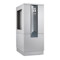
The external electric cables to be provided must be fed
through the grommets cut out in the bottom of the rear
panel and then fed into the electrical switch cabinet by
means of the cable duct, which is integrated into the
baseplate of the heat pump.
1 Cable duct
The cables laid in the switch cabinet for the regulator
(patch cable, LIN bus) must be fed through the
grommet cut out in the bottom of the rear panel.
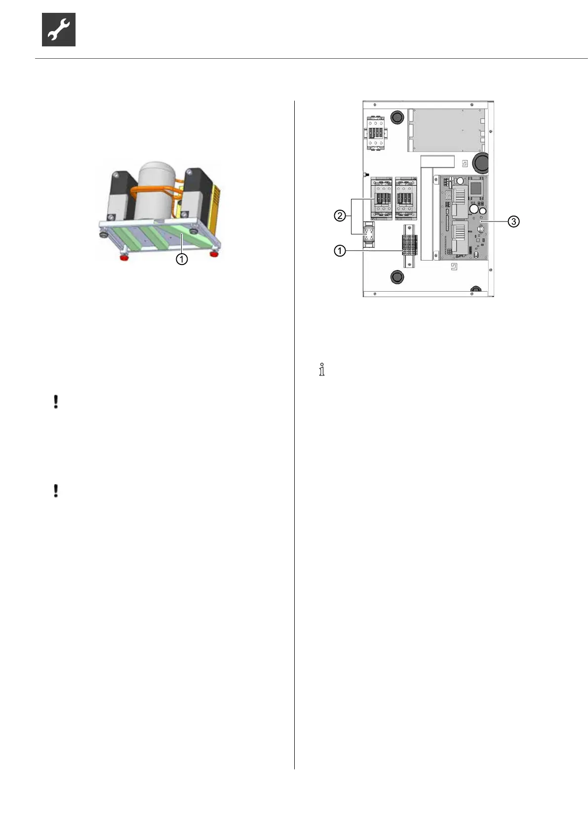
6. Make electrical connections according to the ter-
minal diagram.
“Terminal diagram”, page 48
IMPORTANT
Ensure clockwise rotary eld of the load
power supply (compressor).
Operation with the incorrect rotary direction
of the compressor can cause serious,
irreparable damage to the compressor.
IMPORTANT
The power supply for the heat pump must be
equipped with an all-pole automatic circuit-
breaker with at least 3mm contact spacing to
IEC 60947-2.
Note the level of the tripping current.
“Technical data / scope of delivery“, from
page 22, “Electrics” section
1 Control voltage connection
2 Compressor output connection
3 Regulator board
NOTE
The control element of the heat and heat
pump regulator can be connected to a
computer or network using a suitable network
cable, enabling the heating and heat pump
regulator to be controlled remotely from there.
If such a connection is required, lay a
shielded network cable (category 6, with
RJ-45 connector) up to the control element
while carrying out the electrical connection
work.
7. After completion of all electrical installation work,
close the switch cabinet inside the unit.
8. Screw on the front panel of the unit if no further in-
stallation work inside the unit is to be performed
immediately.
 Loading...


