17
Subject to change without notice | 83053700lUK | ait-deutschland GmbH
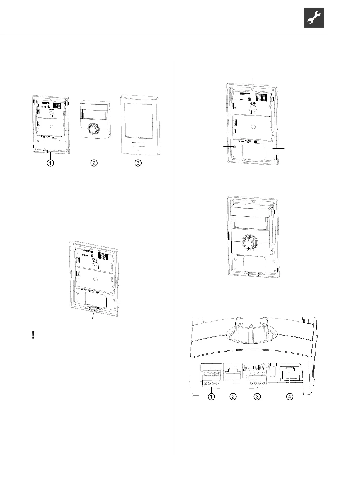
18 Installation of the control
element
The separate package contains:
1 wall bracket
2 control unit
3 cover
1. The cables are laid either through the wall (e.g.
ush cable box) or from underneath.
When routing cables from underneath, you must
break out the plastic strip (hatched area) on the
wall bracket.
IMPORTANT
Mount the wall bracket with control panel
only vertically on a wall!
2. Fasten the wall bracket using the 3 screws (plus
dowels) included in the scope of delivery.
“Wallbracket for control unit”, page 42
3. Plug the control unit onto the wall bracket.
Connections
The connections are located on the underside of the
control unit:
1 Connection room control unit
RBE RS 485 (accessory)
2 RJ45 connection cable to the network link
3 Connection LIN bus to the regulator board
4 RJ45 connection regulator board
 Loading...


