13
Subject to change without notice | 83053700lUK | ait-deutschland GmbH
5. Use the insulating tape supplied to insulate the
connection clip. Use the enclosed fastening mate-
rials to additionally x the insulation.
NOTE
We recommend completing step 5 after the
leak test.
NOTE
The heat source and heating side must be
insulated from the heat pump; to this end
we recommend using the IPFK hydraulic
connection set in our range of products (not
included in the scope of delivery).
6. Install shut-o devices at the heating circuit.
7. Install shut-o devices at the heat source.
8. Place a bleeder at the highest point of the heat
source in the heat source outlet.
9. We recommend installing a dirt lter (screen size
0.9 mm) on the heat source inlet connection.
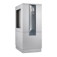
The hot water and heat source connections are
marked accordingly on the unit.
For the positioning of the connections: “Dimen-
sional drawings“, from page 38, for the respec-
tive model
16.4 Installing the housing
NOTE
Remove the protective lm from all facing
panels.
NOTE
The screws for installing the heat pump
housing are included in the scope of delivery.
1. Position the insulation included in the scope of
delivery under the baseplate.
NOTE
Before screwing on the side panels, feed the
patch cable and + LIN bus cable through the
rear panel!
“17 Electrical connections”, page 15
2. Screw the two side panels onto the back panel
using 3 screws for each.
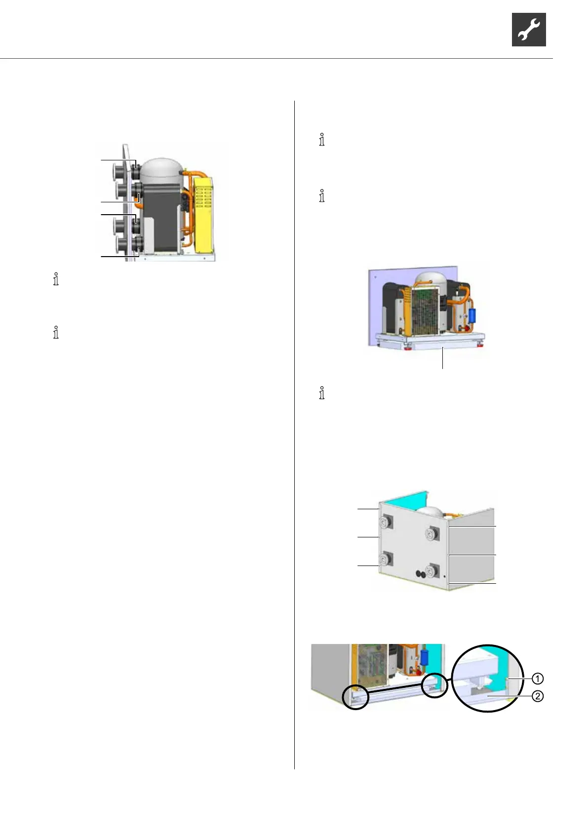
3. Mount the prole rail onto the front of the unit,
between the two side panels, using 2 screws for
each side.
1 Screw
2 Prole rail
 Loading...


