55
VD1
/1.3
VD2
/1.7
K2-A1
/1.7
K1-A1
/1.3
L Reg
/1.15
N Reg
/1.15
MOT
/1.15
A2
/1.7
A2
ASD
/1.15
B1-11
/1.15
1
-X7
2
L
-X0
3
N
N
PE
PE
13
14
-K3
9
A1
A2
-K0
VD1
-X1
VEN
A1
A2
-K1
VD1
1 2
/1.4
3 4
/1.4
5 6
/1.4
21 22
/1.5
VD2
-X1
A1
A2
-K2
VD2
1 2
/1.8
3 4
/1.8
5 6
/1.8
21 22
/1.9
N..
-X1
P
b2 c4
a1
-F1
HDP
HD.
ND.
-X1
P
c4 b2
a1
-F2
NDP
L..
VBO
A1
A2
-K3
1 2
/1.11
3 4
/1.11
5 6
/1.11
13 14
3
L
-X0
1
2
-F6
9
-X7
L L
10
MOT
-X2
ASD
EVU
1 2
/1.2
3 4
/1.2
5 6
/1.2
-
EVU
K1
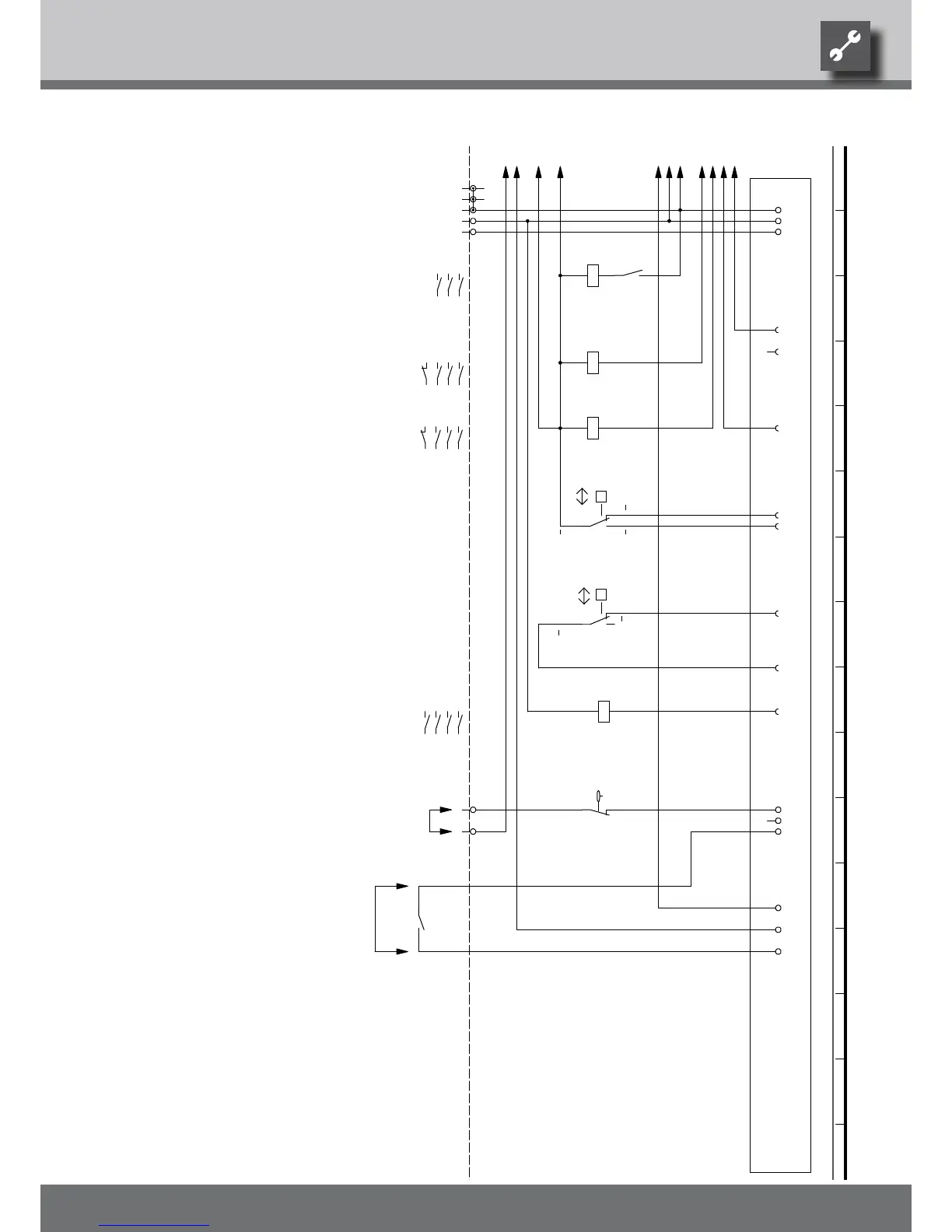
External flow rate switch; bridge if no switch can be connected.
Legend:
+
Function
F2
2
Flow rate switchF6
Energy supplier contact; closed on release; bridge if no blocking interval
Operating materials
1,2,3,N,PE; power supply, controller
Controller board; Attention: I-max = 6A/230VAC
Contactor for compressor 1
UK817329
F1
1
HDP
1~/N/PE/230V/50Hz
EVU
Contactor, well / brine pump
Contactor for compressor 2
3
K0
NDP
-A1
/1.7
A1
1~N/PE/230V/50Hz
Mains contactor, condenser
Low-pressure switch
K2
2
230VAC
+
VD1
1
VD2
DFS
-
High-pressure switch
DFS
K3
We reserve the right to make technical changes.
UK830509/200114 © Alpha-InnoTec GmbH
Circuit Diagram 2/3 SWP 540 – SWP 820 · SWP 330H – SWP 500H