39
L Y2
4
1
5
2
-F12 -F10 -F11
A1
A2
P
14
11
-X2
Name
A1
2
2
BUP
TBW
TBW
Cut out auxiliary heating
EVU
2
N
-T2
ZUP
A3
MOT
TBW
ZW2/SST
Diverting valve for domestic hot water; internally wired
F12
ASD
HUP
GND
VBO
Heating circuit circulation pump; internally wired
L1
GND
GND
Domestic hot water sensor/thermostat; internally wired
Only on 10 kW unit: Phase sequence relay; if phase sequence in the order of 11 + 14 is closed
FP1
1
Control signal of additional heat generator 1; internally wired
L1
ZW1
-X3
5
BUP
TA
6 - 10 kW
X7:L1,N,PE
ZW1
X7:PE,N,L1,L2,L3
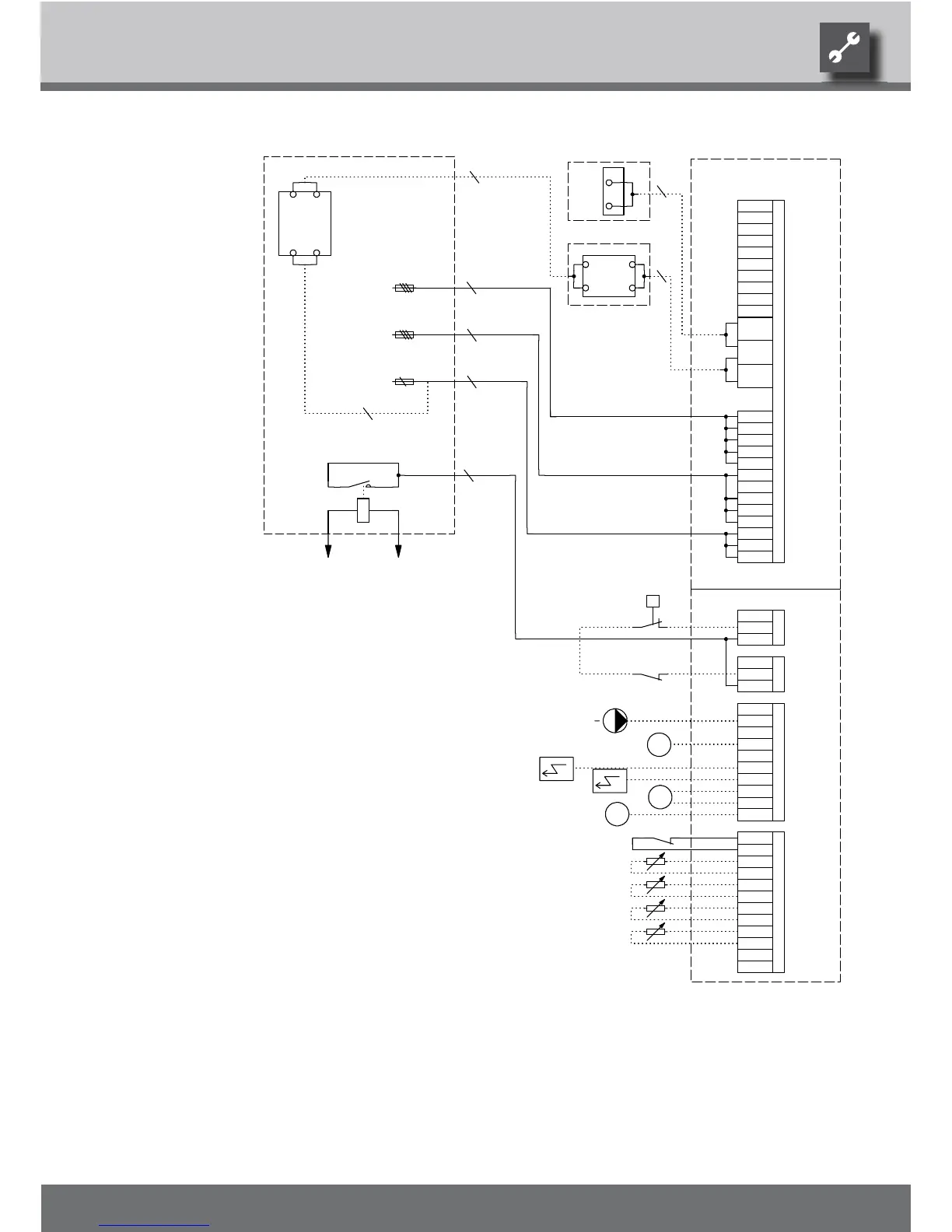
Terminal strips on controller board (see sticker)
Auxiliary heating 3 x 400V
Terminal strip in switchbox of heat pump; N/PE distribution for external 230V units
-Y3
EVU
ZW2/SST
N
PE
Control signal of additional heat generator 2 (alternative is general malfunction)
L3
L1
Brine circulation pump
Auxiliary circulation pump
Heat station brine 6 - 10 kW
T2
ZUP
X7
M
X7:PE,L1,L2,L3
B1
2
A2
-X0
MA1
N
F11
X0-X4
Y2
A1
Terminals
VBO
ZW2/SST
Control 230V
Power supply compressor 3 x 400V; Attention: Right-hand rot. field is mandatory!
Terminals in heat pump switchbox
PE
Y3
A2
Legend:
RFV
With cooling option: Room thermostat; bridge if not connected
BUP
3-pol. Cut out compressor; Attention: Right-hand rot. field is mandatory!
GND
N
RFV
6,8,10 kW: C10 A
N
PEX
EVU
1~N/PE/230V/50Hz
24V
FP1
PE
Energy supplier contact; closed on release; bridge if no blocking interval
TRL
3
F10
GND
Controller board; Attention: I-max = 6A/230VAC
B10 A
UK831136
RFV
PE
Cut out controller unit
Accessories with cooling option: Dewpoint monitor; bridge if not connected
Accessories: Transformer for dewpoint monitor
GND
ZW1
PE
ASD
HUP
MIS
2
TB1
M
TB1
-X7
3~PE/400V/50Hz
ASD
TRL
4
PE
2
MZ1/MIS
Function
TB1
-Y2
Pump for mixing circuit 1
External return sensor
MA1/MIS
TA
Impressed current anode monitor
MZ1
N
TA
Overload protection; internally wired
FP1
6,8,10 kW: C10 A
Sensor mixing circuit 1
External sensor
PEX
3
Sub-distribution unit internal installation
230V
-X4
B1
Brine pressure pressostat; provided by cust. if necessary
Charge/discharge/cooling mixer 1 closed
3~N/PE/400V/50Hz
A3
MOT
Charge/discharge/cooling mixer 1 open
L1
PE
L1
N
L1
Accessories: Remote control
PE
N
L2
L2
L3
ZIP
M
ZIP
Circulation pumpZIP
We reserve the right to modify technical specifications without prior notice.
UK830501/200520 © Alpha-InnoTec GmbH
Terminal diagram WZS 60H(/K) – WZS 100H(/K)
 Loading...