We reserve the right to modify technical specifications without prior notice.
UK830501/200520 © Alpha-InnoTec GmbH
L1
L2 L3 N PE
1
2
-K1
7
-X100
A1
A2
L1 L2 L3
T1 T2 T3
-N1
3
4
M
3
T1 T2 T3 PE
-M1
VD1
5
6
L1
-X7
L2 L3 N
1
2
-K5
15
PE
3
4
5
6
L
-X0
L
-X7
N
N
PE
PE
VD1
-X1
14 12
11
N..
-X1
2
P
+-
b2 c4
a1
-F1
HDP
HD.
3
-X200
VBO
-X1
A1
A2
-K1
VD1
1
-X200
12
2
34
2
56
2
13 14
ND.
-X1
5
P
-+
c4 b2
a1
-F2
NDP
L..
4
-X200
L
-X0
L L
MOT
-X2
ASD
EVU
HUP
-X3
M
1
L
N
PE
-M4
M
1
br bl PE
br
wt
bl
bk
-M5
HUP
GND
/2.14
0-10V
/2.14
BUP
-X3
br sw bl
-Y1
VBO
-X1
7 8
M
1
L
N
PE
-M3
9
-X200
12
4
34
4
56
4
13 14
ZW1
-X3
ϑ
-STB
4
-X7
A1
A2
-K5
ZW1
MA1
-X3
MZ1
M
1
A
Z
N
PE
-M16
MIS
L
/2.1
N
/2.1
-N1
sw
K1
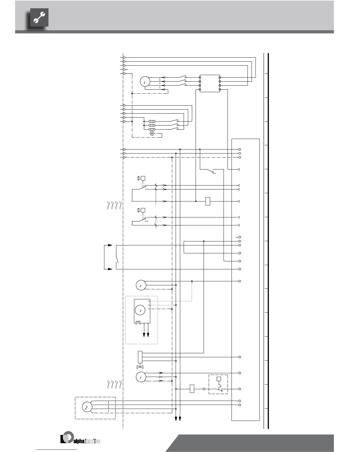
Terminal strip in switchbox of heat pump; N/PE distribution for external 230V units
UK817338a
MIS
Heating pump; not applicable with optional integrated heat quantity meter
ZW1
Starting current limit
Contactor for compressor 1
sw
M16
Brine pump
Contactor for auxiliary heating
Mixer; installed with cooling option
K5
VD1
Legend:
b
l
N1
Safety temperature limiter heating element
Diverting valve for domestic hot water
M1
ZW1
HUP
3~PE/400V/50Hz
X7
Auxiliary heating
gr
STB
R1
VD1 Compressor 1
M3
Operating materials
M4
BOSUP
Power supply compressor; right-hand rot. field is mandatory!
Controller board; Attention: I-max = 6A/230VAC
F4 Overload relay for compressor 1
Function
3~N/PE/400V/50Hz
Controller supply
F1
3~N/PE/400V/50Hz
EVU
High-pressure switch
Heating pump energy efficiency; installed with optional integrated heat quantity meter
sw
M5 HUP
1~N/PE/230V/50Hz
123
F2
bl rt
EVU
Power supply aux. heating
br
B1
-R1
s
w
230VAC
A1
1~N/PE/230V/50Hz
Phase sequence relay; if phase sequence in the order of 11 + 14 is closed
Low-pressure switch
b
r
-A1
~PE/400V/50Hz
HDP
sw
NDP
Energy supplier contact; closed on release; bridge if no blocking interval
1 2 3 4 5 6 7 8 9 10 11 12 13 14 15 16
WZS 100H(/K) Circuit diagram 1/2
 Loading...