43
We reserve the right to modify technical specifications without prior notice.
UK830501/200520 © Alpha-InnoTec GmbH
L
/1.16
N
/1.16
X1
X2
X3
+
-
X4
GND
1
0
PEX
-X4
GND
ϑ
RFV
-X4
-R10
RFV
GND
ϑ
TB1
-X4
-R13
TB1
GND
TR
1
-X7
2 3
ϑ
TBW
-X4
-R9
TBW
GND
ϑ
TA.
-X4
-R8
TA
GND
ϑ
TRL
-X5
-R4
TRL
GND
ϑ
TVL
-X5
-R5
TVL
GND
ϑ
THG
-X5
1
-R6
THG
GND
2
-X300
ϑ
TWA
-X5
5
-R11
TWA
GND
6
-X300
CW.
-X5
-R12
GND
ϑ
TWE
-X5
3
-R7
TWE
GND
4
-X300
AIn
-X6
yellow
white
Green
Brown
-B2
Flow sensor
GND
AO1
0-10V
/1.12
GND
/1.12
AO2
-X6
GND
R11
Analogue output 2
-Y2
AIn
External sensor
Voltage supply for impressed current anode
AO2
T1
TA
5
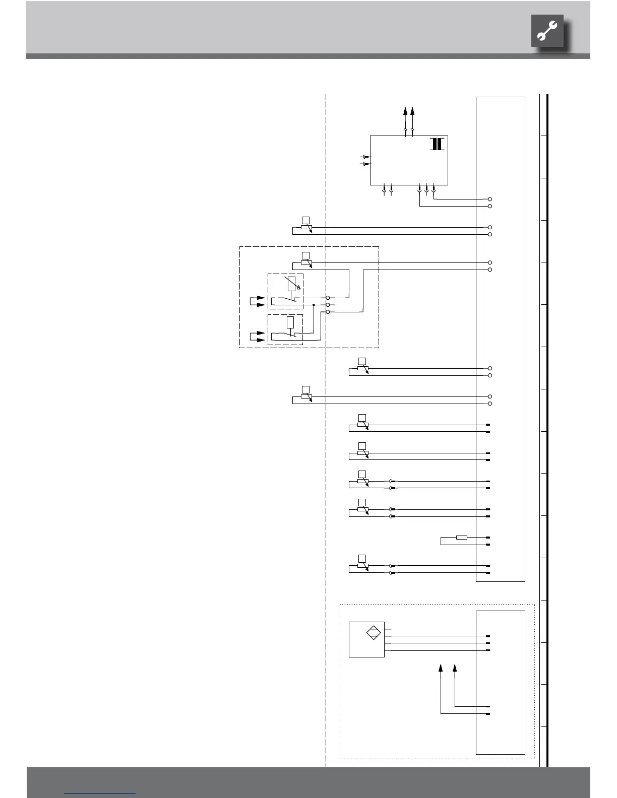
Legend:
-Y3
Y2
Accessories: Remote control
A1
Y2
Analogue input
Accessories with cooling option: Dewpoint monitor; bridge if not connected
CW
4
-A1
TB1
R13
Operating materials Function
-CW
Y3
-Y3-Y2
L
R8
TRL
Controller board; Attention: I-max = 6A/230VAC
R4
TBW
Anode connection
A6
-X2
Sensor mixing circuit 1; installed with cooling option
UK817338a
TWE
R10
AO1 Analogue output 1
Flow sensor; installed with optional integrated heat quantity meterB2
-T1
-A6
Return sensor
Comfort plate; installed with optional integrated heat quantity meter
With cooling option: Room thermostat; bridge if not connected
R5
X2
Heat source input sensor
Heat pump coding; WZS - 1370 ohm
R9
RFV
Flow sensor
R6 Hot gas sensor
R12
R7
Heat source output sensor
Domestic hot water sensor
TVL
THG
TWA
1 2 3 4 5 6 7 8 9 10 11 12 13 14 15 16
Circuit diagram 2/2 WZS 100H(/K)
 Loading...