33
7.14 ALPHA CONTROLS (if fitted) - Fig. 24
Note: For replacement only use an Alpha single channel control. Do not fit a two channel control.
1. Gain access behind the control panel as described in Section 7.1.
2. Remove the three screws securing the terminal block cover at the rear of the panel.
3. Disconnect the wiring from the control.
4. Remove the three control retaining screws and withdraw the control from the panel.
5. Fit the new control, and connect the wires as follows:-
Blue to terminal 1, Brown to terminal 2 and Red wires to terminals 3 and 4, (or as per the instructions supplied with the
control).
6. Re-assemble in reverse order. Refer to the User's instructions and the boiler's control cover to set the control.
7.15 DHW TEMPERATURE SENSOR - Fig. 32
1. The DHW sensor is positioned in the hot water outlet pipe to the left of the flow switch, see Fig. 34. Unplug the two
connections and unclip the sensor from the pipe.
2. Re-assemble in reverse order with a new sensor.
7.16 COMBUSTION CHAMBER INSULATION
Gain access to the combustion chamber as described in Section 7.1.
Front panel insulation - Fig. 29
1. Remove the electrodes from the combustion chamber front as described in Section 7.3.
2. Remove the four screws securing the burner.
3. Carefully remove the insulation.
Back panel insulation - Fig. 33
1. Remove the combustion chamber front/burner assembly.
2. Carefully remove the insulation, suction applied to the centre of the insulation will aid this.
Fit a new panel and re-assemble in reverse order.
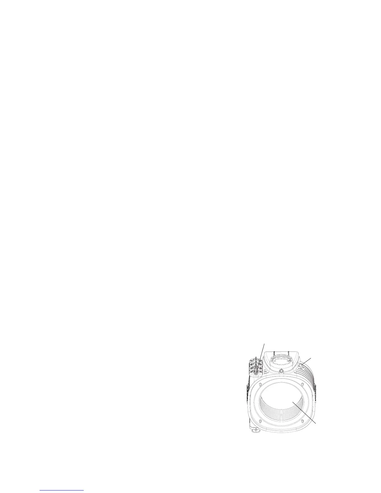
7.17 HEAT EXCHANGER THERMAL FUSE - Fig. 33
Note: If the thermal fuse has failed or operated, the heat exchanger must be replaced. Do not attempt to remove the thermal
fuse. Disturbing the sealant securing the thermal fuse will invalidate the warranty.
1. Gain access behind the front casing as described in Section 7.1.
2. Disconnect the wire from the thermal fuse and remove the heat exchanger as described in Section 7.19.
3. Fit a new heat exchanger and re-assemble in reverse order.
7.18 DHW FLOW SWITCH - Fig. 32
1. Gain access behind the front casing as described in Section 7.1.
2. Isolate the mains water supply and open all hot taps to drain any water from the boiler.
3. Disconnect the wires from the switch.
4. Undo the union nut and remove the fixing screw from the bottom of the switch.
5. Remove the two 4 mm socket head capscrews securing the top switch and lift
out the switch.
6. Fit the new switch and re-assemble in reverse order.
7.19 PRIMARY HEAT EXCHANGER - Figs. 30, 33
1. Gain access behind the room sealed chamber panel as described in Section
7.1 and drain the boiler heating circuit as described in Section 7.2.
2. Remove the burner as described in Section 6.2 (Routine Servicing).
3. Unplug the connections from the flue temperature sensor and thermal fuse,
see Fig. 30.
4. Disconnect the condensate drain pipe by pulling its rubber connector from
the heat exchanger.
5. Remove the screws securing the ignition generator bracket, disconnect the
earth lead and remove the ignition generator.
Alpha InTec C and X - Component Replacement
Fig. 33
Thermal fuse