R
5
4
3
2
1
R
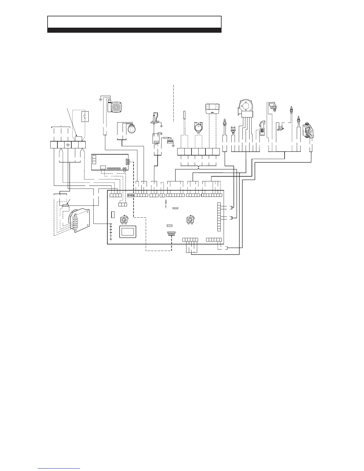
Alpha controls (optional)
Remove link
to connect
Alpha controls
Flue
Sensor
Flow
Sensor
DHW
Sensor
Heat
Exchanger
Thermal
Fuse
Overheat
Thermostat
Low voltage electrical connections
230 V electrical connections
DHW
Flow
Switch
System
Pressure
Switch
Br
Bl
Bl
Br
W
G Or
Bk
Br
Bl
W
G Or
Bl
Bl
Gy
Bk
Gy
W
W
G
Gy
Br
R
Bk
Br
R
R
Gy
R
Bk
Or
G
Gy
Bl
R
Br
R
Br
Bk
R BrBl
Br
R
Bl
Bl
G/Y
Bl
Gy
21
Colour Code
Br Brown
Bk Black
Bl Blue
R Red
Or Orange
G Green
G/Y Green/Yellow
W White
Gy Grey
Remove the link between terminal
block connections 1 and 2 if the
optional Alpha Climatic control or
230 V room thermostat is used.
X21
X26
50 51 52 53 54 55 56 57 58
Relay Board
(optional)
X20
X16 X4
2
4
4
2
5
1
1
5
3
3
X12
4
2
3
6
5
17
X18
4
2
3
6
5
178
X14
4
2
3
6
5
1
7
8
9
10
11
X7
4
2
3
6
5
1
X17
3
5
4
1
2
6
X19
2 1
X3
L
N 3
4
X10
X9
X11
X15
1
1
2
2
3
3
Fuse
3.15 AF
Transformer
DHW SET
+
CH SET
+
B A
X5
12
3
4
5 6
X8
1
X6
R2
Alpha
Climatic Control
(optional)
+
-
Fan
8 9 10
11 12
13
1 2
L N
Room
thermostat
(optional)
Link
Supply
230 V
~ 50 Hz
Br
Bl
Boiler
Pump
Diverter
Valve
Br
DHW
CH
Bl
Bk
-UB
PWM
GND
HS
+UB
External
Sensor
(optional)
DHW
Inlet sensor
(optional)