19
Alpha CD13R, 18R, 24R - Installation
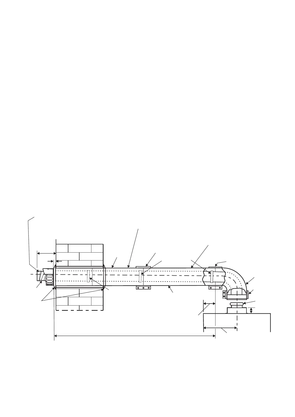
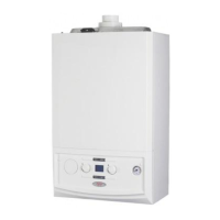
Fig. 4.10 - Side flue
Easy-Flue 45 mm clamp
Easy-Flue
40 mm clamp
and seal
100
195
45
Front of boiler
Extension clamp
Inner seal joint
Inner seal joint
Flue length (L)
90° bend
Seal joint
CD Easy-Flue
Ensure outer flue duct of Easy-Flue is horizontal
Ensure the flue extension slopes
downwards towards the boiler by a
minimum of 25 - 30 mm per metre
CD Flue extension
Flue sealing
collar
Ensure the inner duct within
the terminal is at the top.
The inner duct must
be positioned to slope towards
the boiler
Note:
120
Terminal
20
2. Use the template (supplied with the boiler) to mark the required flue position and cut a 130 mm diameter hole for the
flue (use a 127 mm core drill). The size of the hole provides sufficient clearance for the clamps on the flue extension to
pass through the hole.
3. Determine the overall flue length as described in Section 4.6, paragraph 2 to determine the number of Alpha CD
750/1000 mm flue extensions required.
4. Assemble the flue extensions together by locating the inner duct into the seal joint and secure each extension together
with the clamps supplied (three screws). Ensure that the clamps are positioned centrally over the joints.
Note: If it is required to cut an extension, DO NOT cut the end of the inner duct that incorporates the seal joint. Ensure
the inner duct end without the seal joint is cut so that it is 15 mm longer than the outer duct.
5. Adjust the telescopic section of the Easy-Flue to the required length and secure the Easy-Flue with the sealing tape
supplied. Fit the Easy-Flue to the extensions by locating the inner duct into the seal joint and secure with the clamp
(three screws), ensuring it is located centrally over the joint.
6. Mark the end of the flue assembly 'TOP' where it is connected to the boiler,so that the 'TOP' of the flue terminal is
aligned with the 'TOP' at the boiler end of the flue assembly.
7. Pass the complete flue assembly through the wall.
8. Position the seal and clamp (two screws) supplied, over the bend. Fit the bend to the boiler and rotate to the correct
position and secure in position using the seal and clamp, ensuring that the seal is positioned centrally over both the bend
and adaptor.
9. Slide the clamp (three screws) over the outer duct and pull the flue assembly towards the bend, locating the inner duct
into the seal joint on the bend.
10. Secure the flue assembly to the bend with the clamp (three screws) ensuring it is positioned centrally over the joint,
ensuring the 'TOP' marked on the outer duct is positioned at the top.
Note: Check the flue terminal protrudes 100 mm out of the wall and that the inner duct of the terminal is positioned
correctly, i.e. the inner duct within the terminal is at the top. See Fig. 4.10.
11. Make good the outside wall by fitting a flue sealing collar onto the location provided immediately behind the flue terminal
grille. Make good the inside wall as required.
Note: If flue sealing collars are being used to make good the inside wall, then they will need to be fitted before
assembling the flue.