28
Alpha CD13R, 18R, 24R - Routine Servicing
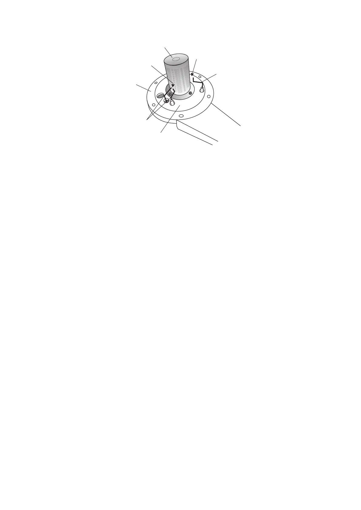
7.4 RE-ASSEMBLE THE BOILER
1. Replace the burner, ensuring it is located correctly and secure it in position using the four screws previously removed.
Important: Before replacing the combustion chamber front assembly, pour at least 200 cc of water into the coils of the
heat exchanger. This is to ensure the condensate trap is full of water before operating the boiler.
2. Replace the combustion chamber front assembly, ensuring it is correctly located.
3. Ensure the electrode lead is connected and the seal is in position in the bottom of the room sealed chamber.
4. Test the connections for gas soundness and re-commission, Sections 5.4 and 5.5.
5. Ensure that the room sealed chamber panel seal is intact and in position, replace the panel ensuring it has been
located correctly and secure it in position with the screws previously removed.
6. Raise the control panel and secure in position with the two screws provided.
7. Replace the front case panel and secure in position.
8. Check the operation of the boiler. (Refer to Boiler Operation, Section 6).
9. Return all controls to their original settings.
To ensure correct and safe operation of the appliance, it is essential that any worn or failed components are replaced with
only genuine Alpha spare parts. Use of non-genuine Alpha spares could invalidate your warranty and may pose a potential
safety hazard.
Fig. 7.2
Flame sensing
electrode
Gap 11 mm
Ignition electrodes
Gap 3 - 4 mm
Burner
Combustion chamber
front assembly
Front insulation
panel