6
L
N
1
2
F2A
3
4
L
N
Alpha CD13R, 18R, 24R - Technical Data
Fig. 2.2
2.4 FLUE LENGTHS
CD Easy-Flue 500 mm with terminal and 90° bend. A CD Easy-Flue 1000 mm with terminal and 90° bend is also available.
CD 750 mm and CD 1000 mm flue extensions are available.
Length of Flue Required:-
Rear Flue (includes terminal) = wall thickness + 170 mm (or 140 mm for CD24R)
Side Flue (includes terminal) = wall thickness + distance between wall and side of boiler + 200 mm
Vertical Flue = distance from top of boiler side panel to required roof position minus 1000 mm for vertical terminal assembly
Maximum horizontal flue length = 12 m.
Maximum vertical flue length including terminal is 15 m.
Each additional CD 90° Bend is equivalent to 1.3 m of flue length.
Each CD 45° Bend is equivalent to 0.9 m of flue length.
The CD Vertical Flue terminal assembly is equivalent to 1 m of flue length.
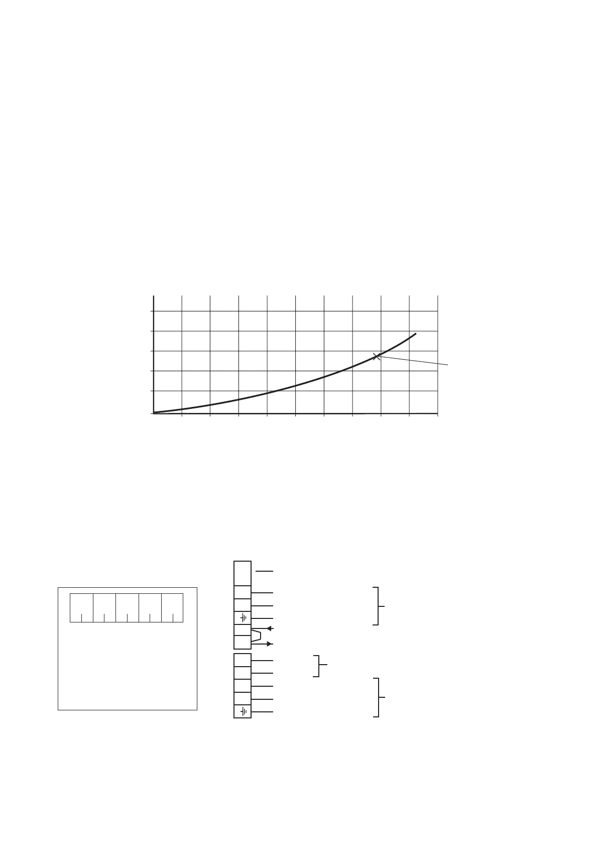
2.5 PRESSURE LOSS ACROSS BOILER
Boiler terminal block
Clock connections
2.6 ELECTRICAL CONNECTIONS
Note: This Appliance Must Be Earthed
An optional integral two channel Clock kit (Part No. 6.1000220) is available if required.
Note: Only use the Alpha two channel clock. Do not fit any single channel clocks.
1. Ensure wires are connected
correctly
2. Only fit the Alpha recommended
2 channel clock. Other clocks
could cause damage.
WARNING
12345
Internal 2 Channel Clock Terminals
White
wire
Grey
wire
Black
wire
Blue
wire
Brown
wire
Fuse - Always t fast blow 2 A
230/240 V ~ 50 Hz
Fuse supply 3 A
Note: To connect external
control, remove link from
terminals 1 and 2 and
connect a 230/240 V
switched live to terminal 1
0
0 200 300100 400 500 600 700 800 900 1000
0.5
1.0
1.5
2.0
2.5
Flow rate (litres/hr)
Pressure loss
(metres head of water)
20°C System design
temperature difference
Note: The pump must
always be connected
to this terminal block
Live (Brown wire)
Neutral (Blue wire)
Earth (Green/Yellow wire)
Switched Live
230/240 V (Ch1 ON)
External Pump
Ch1 OFF
Ch2 ON
Live (Brown wire)
Neutral (Blue wire)
Earth (Green/Yellow wire)
Use only when internal
clock is tted
Fig. 2.1