38
Alpha E-Tec 15, 20, 25R - Component Replacement
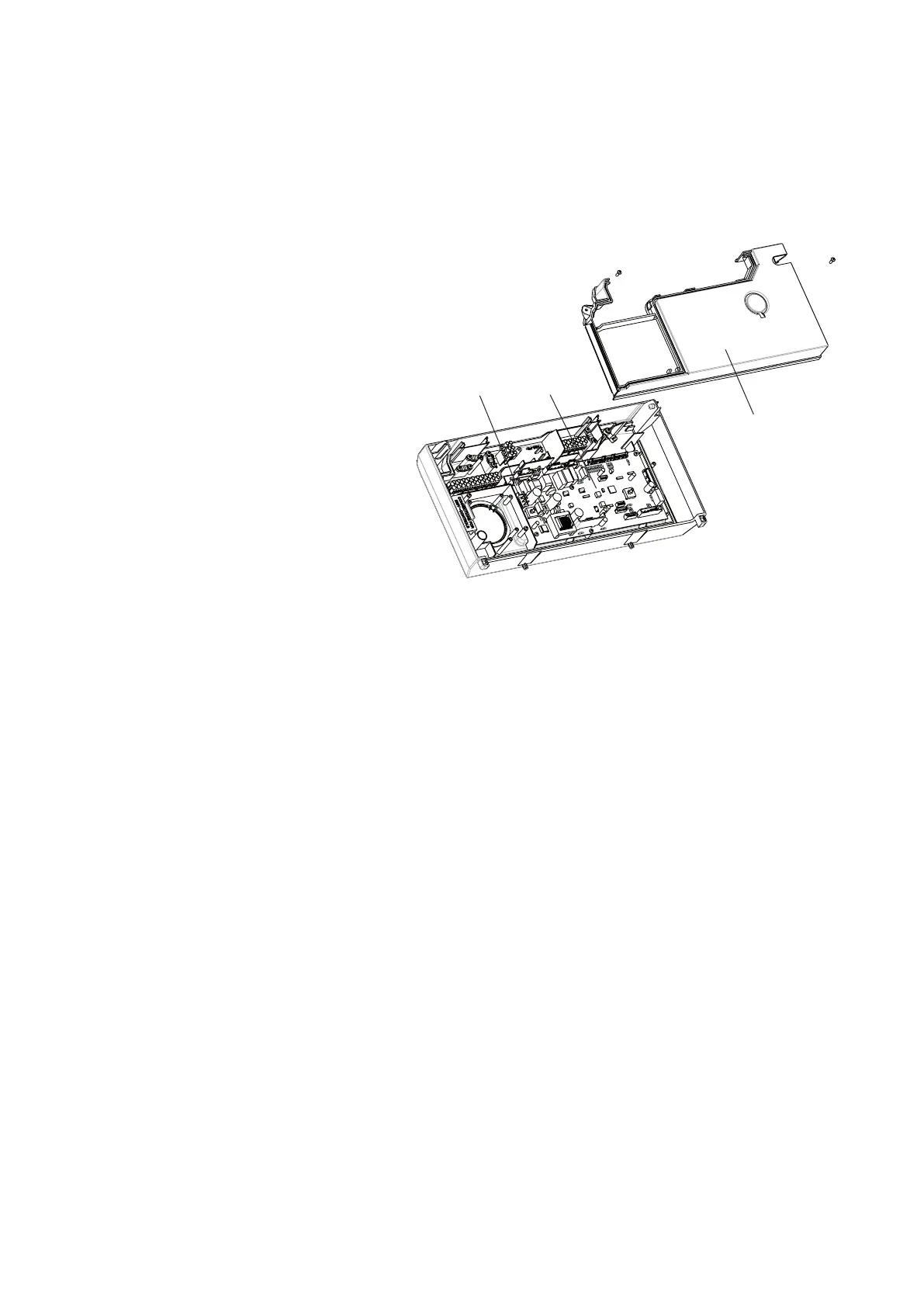
8.7 FUSE - Fig. 8.1
The fuse is located on the PCB.
1. Gain access to the rear of the control panel and PCB as described in Section 8.8.
2. Lift out and remove the fuse. Fit a 3.15 AF 250 V fuse as a replacement.
3. Re-assemble in reverse order.
8.8 PCB - Fig. 8.1
Note: The replacement of the gas valve or PCB must
be carried out by a Gas Safe registered engineer with
the use of a flue analyser.
Gain access as described in Section 8.1.
1. Remove the three screws securing the terminal
cover and remove the cover from the control
panel. See Fig. 5.14.
2. Remove the two screws securing the PCB cover
and remove cover.
3. Remove the PCB retaining screws.
4. Lift the PCB from the control panel and note
the connections before unplugging the wire
connections.
5. Re-assemble in reverse order. Refer to the
wiring diagram in Section 9.1 for connections.
When replacing the PCB cover, ensure no wires
are trapped and all wiring is secured. Secure
cover with two screws - do not over tighten
6. Set the correct parameters for the correct boiler
model as described in Section 6.13.
7. Test the boiler.
8.9 GAS VALVE - Fig. 7.4
Note: The replacement of the gas valve or PCB must be carried out by a Gas Safe registered engineer with the use of a flue
analyser.
Isolate the boiler gas supply and gain access as described in Section 8.1.
1. Disconnect the electrical plug from the gas valve.
2. Remove the gas pipe retaining clip and remove the pipe.
3. Disconnect the gas valve union beneath the boiler.
4. Remove the two screws from beneath the boiler, disconnect the gas valve pressure tube and lift out the valve assembly.
5. Unscrew the brass union from the top of the gas valve and transfer it to the new gas valve using a new washer.
6. Fit the new assembly and re-assemble in reverse order and test for gas tightness.
7. Light the boiler. (Refer to Commissioning, Section 6.4).
8. Check the combustion and carry out the CO
2
setup procedure as described in Section 6.12.
8.10 CONDENSATE TRAP - Figs. 7.4
Gain access as described in Section 8.1. The fan can be removed to aid better access if required. See Section 8.5.
Note: Before removing the trap, ensure that the water from the trap can be contained to avoid spillage.
1. Pull the silicone flue drain hose off the top of the condensate trap and pull the rubber condensate hose adapter out of
the bottom of the boiler. The cable tie is used for production and can be discarded.
2. Remove the trap fixing screw from the bottom of the boiler. Remove the rubber connection from the trap to the heat
exchanger.
3. Lift out the trap being careful not to spill any condense water, remove the trap from the boiler.
4. It is important to clean the trap every time the trap is removed to flush out any deposits from the collection bowl.
Note: Partially fill the trap before replacing.
5. After cleaning re-fit the trap and re-connect the hoses and the locating screw.
Fig. 8.1
PCB fuse PCB
PCB cover