16
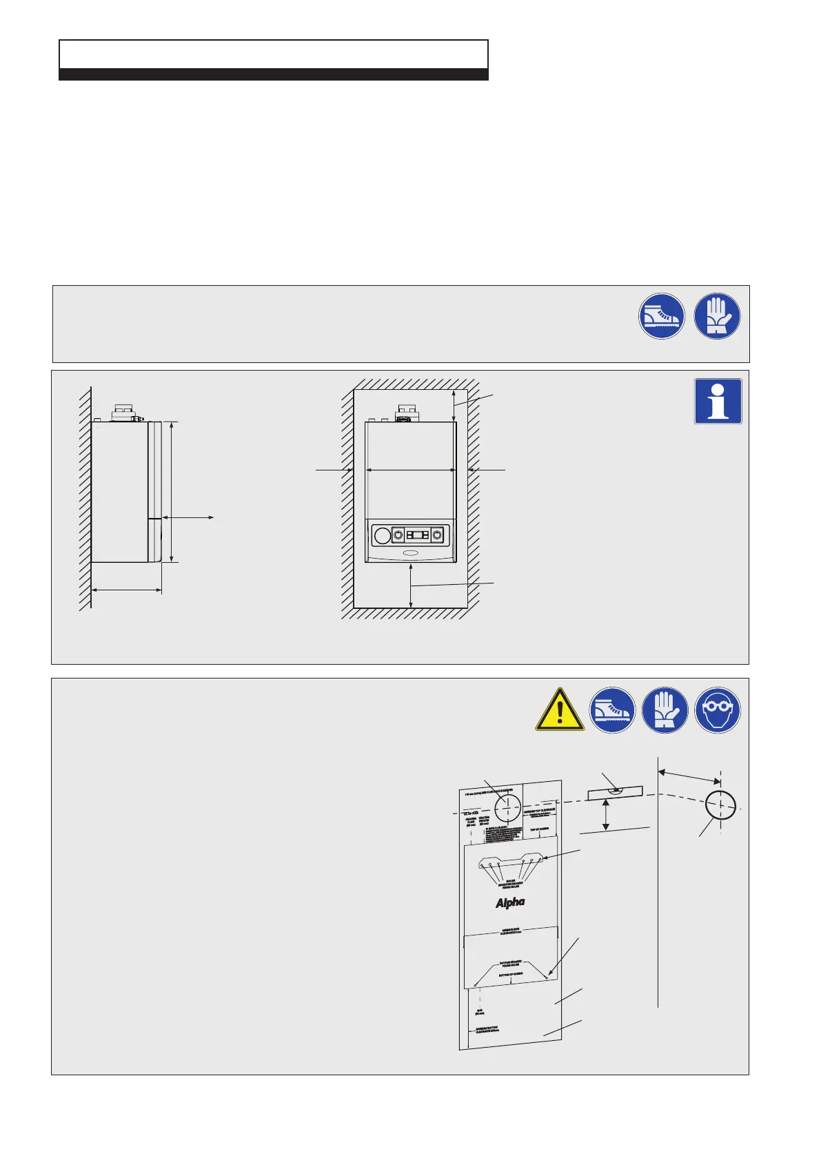
5.3 PREPARE THE WALL - Fig. 5.2
1. Decide upon the position of the boiler taking into account the clearances required
for servicing and the flue terminal position.
2. Tape the template to the wall (ensure it is level and the right way
up) and mark the position of the holes for the boiler mounting
bracket. If rear exit flue is used, mark the position of the hole for
the flue.
3. Side exit flue - Continue the horizontal centre line of the flue
across the wall to the side wall, then along the side wall 138 mm
(ensure the lines are horizontal). This will give the position of the
centre of the hole for the flue.
4. Cut the 110 mm diameter hole (or use a 107 mm core drill) in
the wall for the flue.
Notes: 1. Ensure the hole is horizontal.
2. For internal fitting of the flue, using the flue sealing
collar supplied, cut a 130 mm dia. flue hole using a 127
mm core drill.
5. Drill the fixing holes (10 mm dia.) to accept the No.10 plugs
supplied. Using the screws supplied, fit the mounting bracket.
5 INSTALLATION
Fig. 5.1
Alpha E-Tec 15, 20, 25R - Installation
5.1 UNPACKING
1. The boiler carton also contains the following:-
Connection kit (union bends, washers and gas service cock)
Mounting bracket plus screws and wall plugs
Condensate discharge pipe
Literature pack and Wall template
A suitable Alpha flue system must be selected to use with the boiler.
Notes: a. All flues must be suitable for Alpha condensing boilers.
b. CD 750 mm and 1000 mm flue extensions are available, if required.
Damaged products must not be used.
2. Unpack boiler and remove the loose items, packs and mounting bracket.
Note: The boiler can be stood in an upright position (only while the valves and union bends are not
fitted).
It is recommended that two persons lift the boiler.
5.2 CLEARANCES REQUIRED - Fig. 5.1
Fig. 5.2
Minimum clearances
5 mm 5 mm
250 mm
390 mm
235 mm - Can be reduced to
150 mm when using a
vertical flue
600 mm
Minimum
clearance
of 450 mm
from front
of boiler
300 mm
Template
Outline of
boiler
138 mm
Ensure line is level
Rear exit hole
110 mm dia.
Position of
110 mm hole
to be cut for
side exit flue
141 mm
Boiler bottom
fixing holes
Fixing holes
for mounting
bracket
HEA
TING
FLOW
(22 mm)
HEA
TING
RETURN
(22 mm)
IF SIDE FLUE EXIT
:
110 mm (4.3 in) MIN FLUE HOLE DIAMETER
C/L OF FLUE
MINIMUM
TOP CLEARANCE
TOP OF CASING
MINIMUM SIDE
CLEARANCE 5 mm
BOILER
MOUNTING BRACKET
FIXING HOLES
BOTT
OM BRACKET
FIXING HOLES
BOTT
OM OF CASING
GAS
(22 mm)
MINIMUM BOTT
OM
CLEARANCE 250mm
CONTINUE CENTRE LINE HORIZONTALLY
ACROSS WALL
TO SIDE W
ALL.
THEN HORIZONTALLY
ALONG SIDE WALL
138 mm.
THIS WILL
GIVE CENTRE OF HOLE FOR FLUE.
ENSURE
THE FLUE EXTENSION(S) SLOPE DOWN
TOWARDS
THE B
OILER
BY A MINIMUM OF 25 - 30mm
PER METRE OF FLUE EXTENSION(S) USED.
H
ORIZONT
AL FLUE 235mm
VER
TICAL
FLUE 15
0m
m