9.1 ILLUSTRATED WIRING DIAGRAM
9 WIRING DIAGRAM
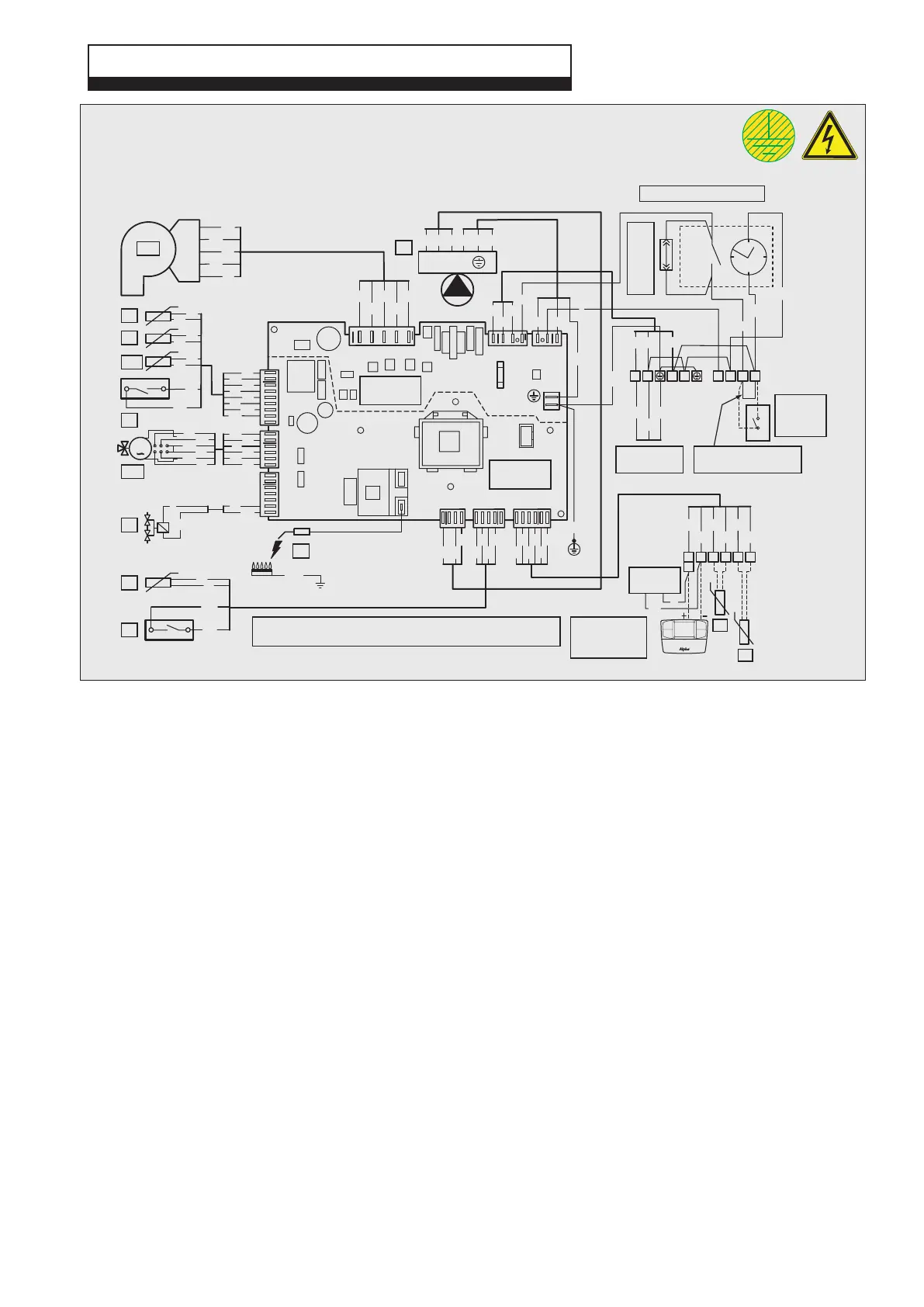
Alpha Evoke 28NX and 33NX - Wiring Diagram
Colour Code
Bk ......Black
Bl .......Blue
Br ....... Brown
G ........Green
Gy ...... Grey
G/Y ....Green/Yellow
Or.......Orange
P ........Purple
R ........ Red
W .......White
Y ........Yellow
Component identification
B1 ............Flow sensor
B2 ............DHW sensor
B4 ............External sensor (optional)
B5 ............Return sensor
B9 ............DHW inlet sensor or FlowSmart cylinder sensor (optional)
B10 ..........Flue sensor
E3 ............Ignition and detection electrode
M1............Boiler pump
M20..........Fan
M30..........3-way valve motor
S4 ............DHW flow switch
S5 ............System pressure switch
T2 ............Ignition transformer
Y1 ............Gas valve
Low voltage
connections
230 V
connections
G/Y
Y
R
Br
Br
Bk
Bl
M
E3
M30
Br
Y
Bk
Br
R
Bl
6
1
9
1
W
P
Or
R
W
Or
P
R
W
P
Fuse
3.15 AF
250 V
-Vcc
HS
+UB
GND
+Vcc
M20
Bl
W
R
Bk
Br
BrR
Bl
W
Bk
1
5
X4
J2J3
X2X3
X1
X6
X5
1
6
1
5
41
7
1
4
1
XF1
T2
Bl
Br
Bk
J1
3 1
Bl
R
Br
Bk
YBr
Gy
Gy
G
G
Bk
R
Y
Y
Or
Or
Y1
W
P
P
P
B1
B5
B10
R
W
R
W
S5
Or
Or
G/Y
G/Y
G/Y
Mains Supply
230 V ~ 50 Hz
Remove link to connect
230 V room thermostat
Room
thermostat
(optional)
Alpha
Climatic Control
(optional)
When an Alpha Climatic control is connected to terminals 40 and 41
remove the link between terminals 1 and 2
Br Bl
Chassis
earth
Y
1
2
5
6
R
(L)(N) (N)(L)
Bl
Br
G/Y
G/Y
Bk
Bl
Bl
L
N
A
B
M1
Y
Br G/Y
Bk
PWM
GND
FEED
Bl Br
LN
B4
B9
R
Or
Y
Bk Or Y
44
40
41
38 39
38
48
For testing
only
Bk
R
3
1
2
4
Programmer clock (optional)
Remove link to
connect clock
Bl
Br
R
B2
S4
G
G
GY
GY
47