6.12 CO2 SET UP PROCEDURE
The air gas ratio of the boiler has been factory set and should not require adjusting during first
commission. If adjustment is recommended or required the engineer must be competent to carry out this
work.
If setting the boiler on a Hydrogen mix installation (G20Y20), for all calibration and combustion checks, refer to the
O2% values for the flue gas analysis. See Section 3.1.
Before starting this procedure please check the following:
The front case is fitted.
The flue system is not blocked or restricted and is to the correct specification.
The gas supply working pressure is correct and the system has been purged.
There is no recirculation in the boiler flue circuit.
The condensate trap is pre-filled.
If the flow temperatures are getting up to maximum operating temperature during the procedure it is possible to open a hot
tap to lose the heat.
Attention: the CO
2 checks must be carried out with the case fitted, while the gas valve adjustments must be carried out with
the front case removed.
Calibration of the maximum CO
2 (nominal DHW output)
Refer to Section 6.6 and enter the chimney sweep mode (with no DHW demand) use the DHW down button to set the output
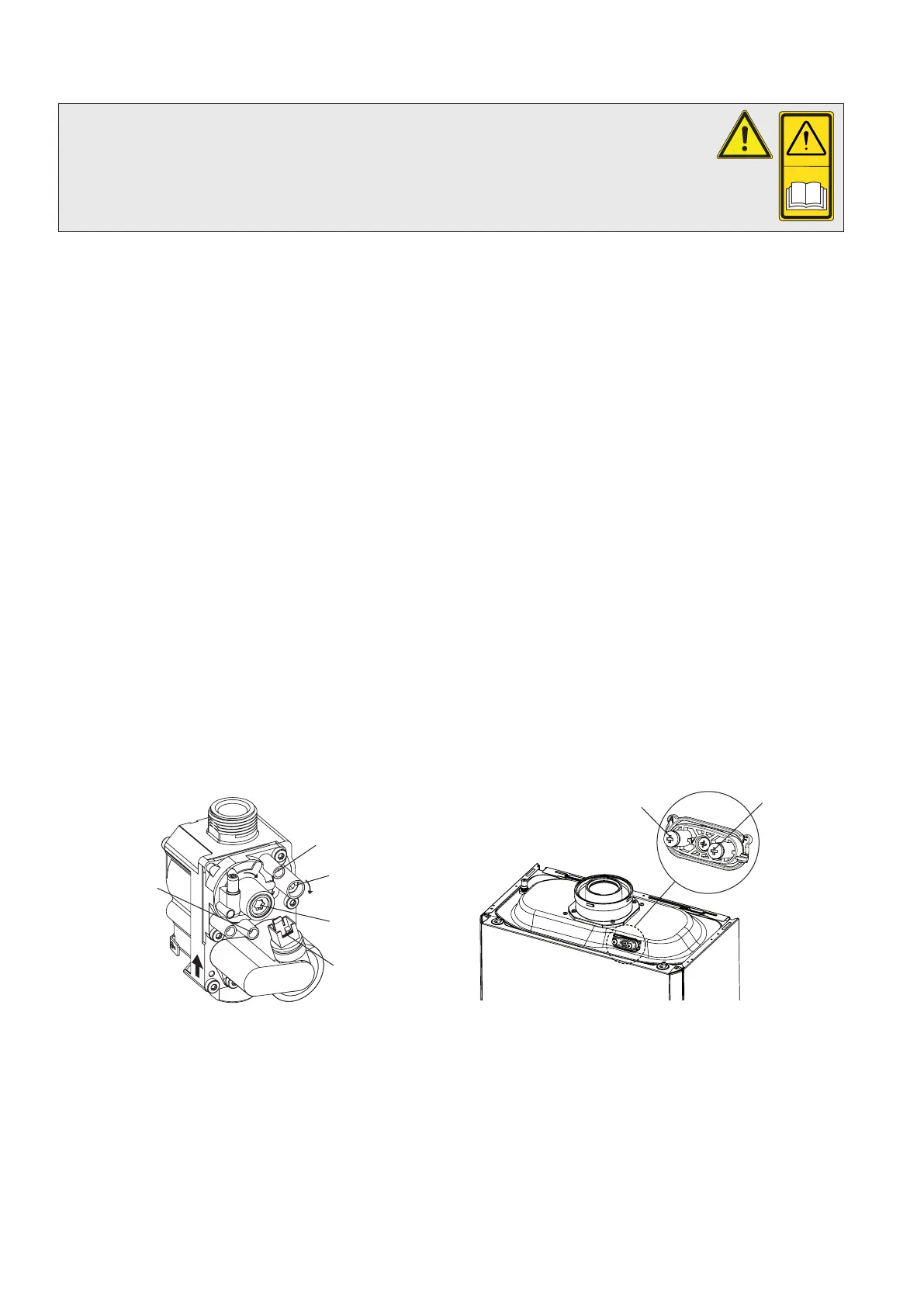
to maximum (99%). Insert the analyser probe into the flue test point (Fig. 6.3) and check that the CO
2 value is as specified
in Section 3.1, otherwise adjust the max CO2 adjuster (Fig. 6.2) To increase the CO2 value, turn the adjustment screw in a
clockwise direction and vice versa to decrease.
Calibration of the minimum CO
2 (minimum output)
When you finish the maximum CO
2 adjustment, while maintaining the chimney sweep function active, use the DHW up
button to set the output to maximum (99%). Insert the analyser probe into the flue test point (Fig. 6.3) and check that the
CO2 value is as specified in Section 3.1, otherwise adjust the min CO2 adjuster (Fig. 6.2). To increase the CO2 value, turn the
adjustment screw (Fig. 6.2) in a clockwise direction and vice versa to decrease it.
For Hydrogen Fuel Installations Only
With Hydrogen mix installation (G20Y20), when setting the maximum, if the value of O
2 as specified in Section 3.1 cannot be
reached with adjusting screw fully open, then additional adjustments are not necessary.
Alpha Evoke 28NX and 33NX - Commissioning
Fig. 6.2 Fig. 6.3
Outlet pressure
test point
Inlet pressure
test point
Wiring plug
+
+
Off/Set adjustment
screw (Min. CO )
2
Gas outlet flow
adjustment screw
(Max. CO )
2
Flue test point
F (+)
Air test point
A (-)
32