Alpha Evoke 28NX and 33NX - Routine Servicing
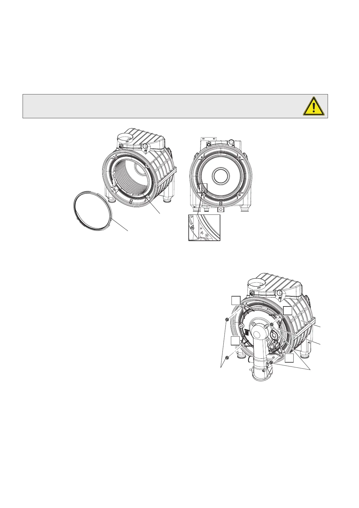
7.6 REPLACING MANIFOLD SEALS - FIG. 7.7
1. Remove the burner as described in Section 7.3.
2. Remove the old seals.
3 Place the module gasket (1) centrally on the edge of the condensation module flange (2).
4. Make sure that the gasket tab with the number 4 printed on it is positioned in its seat on the module flange, identified by
the number 4.
Every time the manifold is opened, the condition and integrity of the ceramic fibres must be verified and replaced,
if necessary. The manifold gasket must be replaced every 2 years. After replacing the external silicone gasket, it is
mandatory to check there is zero spillage.
Fig. 7.6
1
2
7.7 RE-ASSEMBLE THE BOILER
1. Important: Before replacing the combustion chamber front assembly,
pour at least 200 cc of water into the coils of the heat exchanger. This is
to ensure the condensate trap is full of water before operating the boiler.
2. Replace the combustion chamber front assembly, item 2 in Fig. 7.7, to
the condensation module, item (3) in Fig. 7.7, ensuring it is correctly
located and secure with the four 10 mm nuts previously removed.
Tighten the nuts in the sequence A, B, C, D as shown in Fig. 7.7.
The tightening torque when assembling the manifold (2) on to the heat
exchanger (3) must be 4 Nm. Do not exceed 5 Nm.
3. Ensure the injector is in position in the gas valve outlet and re-connect
the gas pipe securing it in position with the spring clips previously
removed.
4. Reconnect the fan wiring plug and air pressure tube, checking the red
pressure signal vent fitting item 20 in Fig. 7.8 is still present and properly
connected.
5. Insert the air inlet pipe into the fan and re-fit the screw securing top of
the pipe.
6. Re-fit the ignition lead to the electrode.
7. Check all the connections are sound and re-commission, Sections 6.3 and 6.8.
8. Raise the control panel and clip into place.
9. Check that the insulation on the back of the combustion panel is intact and in position (it also acts as a case seal), then
place the panel in position over the top pins and secure with the two screws previously removed.
10. Refit the case front panel in position over the top pins and push it back against the side panels, then press around the
button/display area to snap the cover to the control panel and secure in position with the two screws (Fig. 7.1).
11. Check the operation of the boiler. (Refer to Sections 6.5 and 6.6).
12. Return all controls to their original settings.
A
D
C
B
1
2
3
Fig. 7.7
40