EasyManua.ls Logo

Alpha InTec2 35CE User Manual

Alpha InTec2 35CE
68 pages
To Next Page IconTo Next Page
Page #1 background imageLoading...
Page #1 background image
Installation and Servicing
Instructions
InTec² 26CE, 30CE and 35CE
Wall Mounted, Fan Assisted, Room Sealed,
Gas Fired, High Efficiency Condensing Combination Boiler
Nepicar House, London Road,
Wrotham Heath, Sevenoaks,
Kent TN15 7RS
For Technical help or for Service call ...
ALPHA HELPLINE Tel: 0844 871 8764
website: www.alpha-innovation.co.uk
Set for use with Natural Gas
Leave these instructions with the User
0051
These instructions have been carefully prepared but we reserve the right
to alter the specification at any time in the interest of product improvement.
© Alpha Therm Limited 2015.
Part No. 1.035665 ST.001836/000
0415/D346
Alpha InTec² 26CE G.C. No. 47 532 66
Alpha InTec² 30CE G.C. No. 47 532 67
Alpha InTec² 35CE G.C. No. 47 532 68
Question and Answer IconNeed help?

Do you have a question about the Alpha InTec2 35CE and is the answer not in the manual?

Alpha InTec2 35CE Specifications

General IconGeneral
Boiler TypeCombi
MountingWall-mounted
Central Heating Output28 kW
DHW Output35 kW
ErP RatingA
Flow Rate14.1 l/min
Weight32kg
Warranty5 years
Fuel TypeNatural Gas
Efficiency Rating93%

Summary

BENCHMARK SCHEME

Code of Practice

Explains responsibilities for installation, commissioning, and servicing.

Benchmark Commissioning and Servicing Section

Highlights requirements for installation, commissioning, and servicing for warranty.

1 INTRODUCTION

IMPORTANT

Stresses the importance of following instructions for warranty and legal compliance.

2 TECHNICAL DATA

2.1 TECHNICAL PERFORMANCE DATA

Provides performance specifications for Natural Gas and LPG operation.

2.2 PHYSICAL DATA

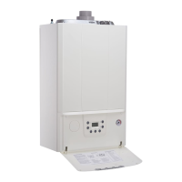
Details the physical dimensions, clearances, and weights of the boiler.

3 GENERAL BOILER INFORMATION

3.2 ELECTRICAL SUPPLY

Details electrical supply requirements, earthing, and connection methods.

3.4 FLUE SYSTEM

Outlines flue system installation in accordance with BS 5440:1 and component details.

4 INSTALLATION

4.2 CLEARANCES REQUIRED

Shows minimum clearances required around the boiler for installation.

4.6 FIT THE FLUE

Instructions for fitting the flue assembly horizontally.

5 COMMISSIONING

5.1 FILL THE SYSTEM

Step-by-step guide to filling and venting the heating system and boiler.

5.5 INITIAL LIGHTING

Step-by-step guide for initial boiler start-up and mode selection.

6 ROUTINE SERVICING

Combustion check

Details the procedure for connecting a flue gas analyser and performing combustion checks.

7 COMPONENT REPLACEMENT

7.3 IGNITION AND SENSING ELECTRODE

Details the procedure for replacing the ignition and sensing electrode.

7.8 PCB

Details the procedure for replacing the Printed Circuit Board (PCB).

7.9 GAS VALVE – BURNER INJECTOR

Instructions for replacing the gas valve and burner injector.

10 SHORT PARTS LIST

9 ERROR CODES AND FAULT FINDING

9.1 INITIAL FAULT FINDING CHECKS

Basic checks to perform before using error code tables.

9.2 ERROR CODES AND FAULT FINDING

Lists error codes, their descriptions, and possible causes.

9 IMPORTANT NOTES

GAS LEAK

Emergency procedure for gas leaks.

10 GAS SAFETY REGULATIONS

Legal requirements for gas appliance installation and servicing.

2 OPERATING THE BOILER

3 HEATING AND HOT WATER TEMPERATURE

Related product manuals