15
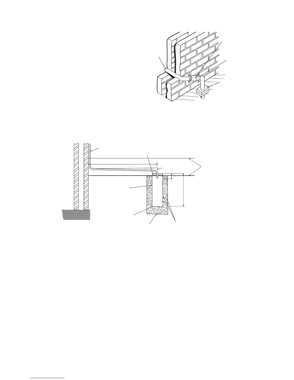
Fig. 3.8 - External soakaway
Alpha InTec² 26E, 30CE and 35CE - General Boiler Information
Ground level (either/or)
22mm termination from boiler, increase to 32 mm if external
2½ fall
O
25mm
300mm
Two rows of 3 x 12mm
holes at 25mm centres,
50mm from the bottom
of the tube. Holes to face
away from house.
Cement mortar sealing
100mm plastic tube
Bottom of tube sealed
Soakaway depth 400mm
filled with limestone chippings
500 mm min.
Optional Condensate Trace Heating Kit
An optional Alpha trace heating kit is also available
to prevent the condensate from freezing.
The control of this kit works with a unique patented
design using the boiler PCB to control the trace
heating. The outside weather probe measures the
external temperature, activating the trace heating
cable only when the boiler is in operation and
producing condensate. This feature together with
the latest technology variable resistance heating
cable ensures only a small amount of electrical
energy is used.
If the external temperature drops below 2°C
and the boiler is on, the relay PCB is operated
and voltage is supplied to the trace heating wire
causing it to heat up and prevent the condensate
from freezing. When the outside temperature rises
to 4°C or the boiler pump stops, the trace heater
is switched off. The connection of the outside weather probe supplied with this kit also enables the weather compensation
feature on the boiler.
Fig. 3.7 - External gully
Open end of pipe
diverted into gully
below grid but above
water level
Use waterproof
pipework insulation
in very exposed
positions
Ensure pipe is
Plastic pipe
(minimum 32 mm)
Minimum gradient 2½°
3.11 DOMESTIC HOT WATER SYSTEM
The minimum flow rate needed for the flow switch and burner to operate is 1.5 litres/min.
If the incoming mains water pressure is above 5 bar a pressure reducing valve must be fitted.
If the mains supply is fitted with a water meter, check valves or loose jumper stop cock, then a DHW expansion device must
be fitted.
Following Part L Building Regulations, where the mains water hardness exceeds 200 parts per million, provision should be
made to treat the feed water to the hot water circuit of combination boilers to reduce the rate of accumulation of limescale.
To ensure economic use, the pipe runs between the boiler and taps should be in 15 mm copper pipe and be as short as
possible. Where possible the pipework should be insulated to reduce heat loss.
All taps and mixing valves used with the hot water system must be suitable for operating at a mains pressure of up to 8 bar.
Showers - A shower may be used with the boiler if required.
If a loose or flexible head type shower is used it may require the fitting of a double check valve, to comply with Water Bye Law 17.
Bidets - No anti-syphonage arrangements are necessary, provided the outlets are shrouded and it is not possible to attach
a temporary hand held spray. A supply of direct mains fed hot and cold water is permitted provided the appliance is of the
over-rim flushing type.
Before the mains water supply pipe is connected to the boiler, it should be thoroughly flushed out to avoid the danger of dirt
or foreign matter entering the boiler.