3
Alpha InTec² 26CE, 30CE and 35CE
The temperature of the hot water to the taps can be adjusted by turning the hot water selector switch (item 5 in Fig. 1) to the
required value shown on the display in °C.
When a tap is opened the display will indicate the temperature of water in the boiler heating the tap water and not the actual
water temperature to the tap.
The temperature of the central heating water can be adjusted by turning the central heating selector switch (item 6 in Fig. 1).
When the heating is on the temperature of the water leaving the boiler to the radiators will be displayed.
If an external weather compensation probe is fitted, indicated by the
symbol (item 18 in Fig. 1) in the display, it will
automatically vary the temperature of the water in the radiators and on a mild day the radiators will not feel as hot as on a
cold day, this is normal and not a fault with the boiler or heating circuit. The room temperature will still be maintained as set
by the room thermostat.
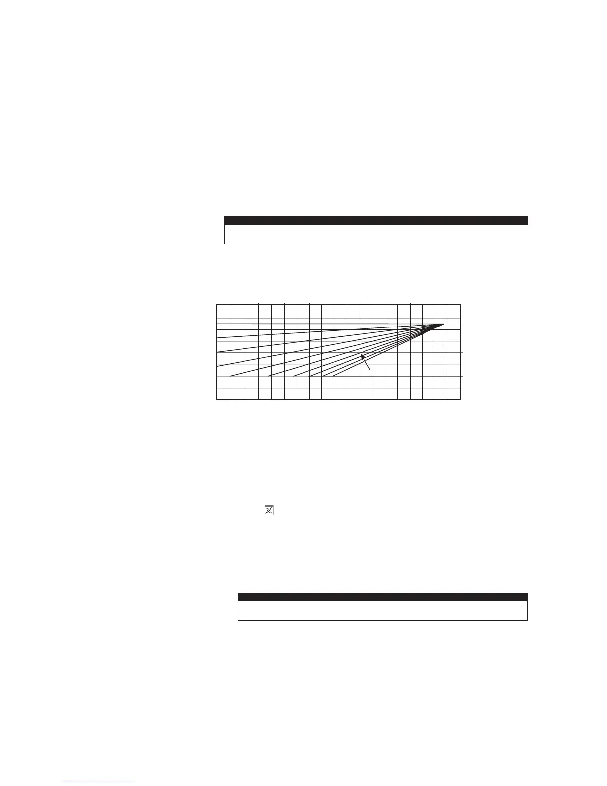
When an external weather probe is fitted, the central heating selector switch (item 6 in Fig. 1) will no longer adjust the flow
temperature in °C, instead the display will show a scale of 1 to 9. Each number corresponds to a line on the graph in Fig 2
i.e. line 6 will give a flow temperature of 60°C when the external temperature is 10°C.
Note: This is the temperature of the water supplied to the radiators and not the desired room temperature. The time and
temperature will still be maintained according to the setting of the room thermostat.
3 HEATING AND HOT WATER TEMPERATURE
Standby - In this mode the boiler will not provide hot water or central heating, but frost protection and pump circulation
features are still active.
Off - In this mode there is electrical power to the boiler but the boiler will not function in any condition.
On - In this mode the boiler can be switched between 'Summer' or 'Winter' settings by pressing the Summer/Winter button
(item 2 in Fig. 1).
Summer setting - The boiler will only provide hot water when a tap is turned on and the central heating will not activate even
if requested by external controls (frost protection and pump cycle are still active).
Winter setting - The boiler will operate in both heating and hot water. The heating will activate depending on the time and
temperature from any heating controls fitted. Hot water will always take priority over heating when a hot outlet tap is opened.
Fig. 2 - External weather compensation probe fitted
Flow temperature (°C)
External temperature (°C)
27 15
5
-510 0 -10 -1520
25 (25)
60 (40)
85 (50)
Flow temperature in brackets
ie. 25 to 50°C range when boiler
is used with a low temperature
system such as under floor heating
Setting 1 to 9 as selected using
the central heating selector switch
4 FILL AND PRESSURISE THE SYSTEM
The system pressure when cold should be 1 bar i.e. within the green section of the pressure gauge.
InTec² CE models have an integrated filling loop underneath the boiler combined with the isolation valves. It may be
necessary to remove the cover under the boiler to expose the filling loop.
Check the loop is fully connected by the sliding brass section between the cold mains inlet and the left primary return
tightening to seal. Carefully open the black tap on the right return connection, now slowly open the left black tap and the
system will begin to fill.
Observe the reading on the pressure gauge and close the tap when the pointer is in the upper green section just above 1 bar.
It is normal for the pressure to rise above the green section when the heating is on as the system expands.
If the system is overfilled and the pressure is greater than the green section when cold the pressure can be reduced by
carefully venting some water from a radiator.
The filling loop can be seen in the Installation instructions Fig. 4.4 in this manual.