24
Fig. 5.2
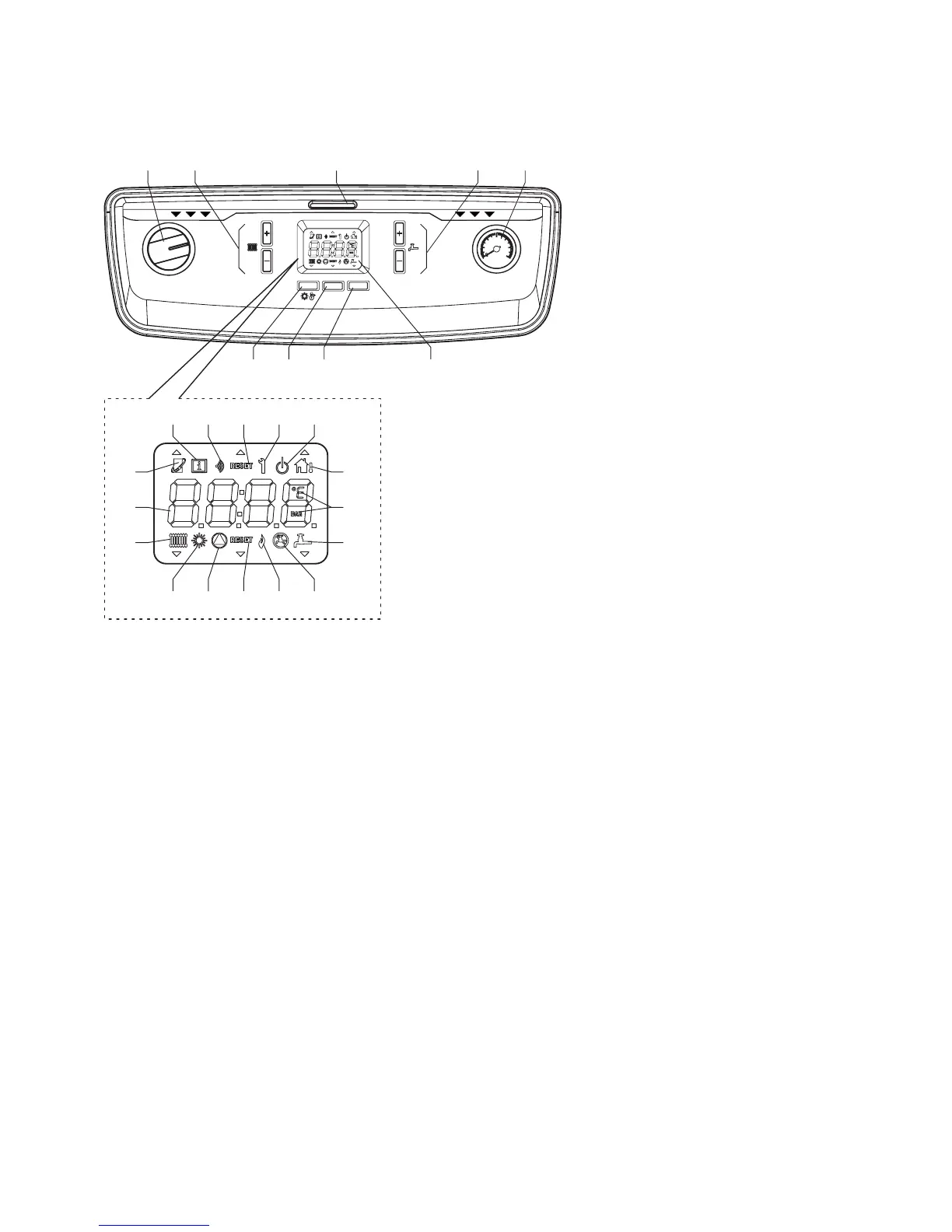
5.4 BOILER LCD DISPLAY AND CONTROL BUTTONS
The boiler display (see Fig. 5.2), is composed of a 4-character display and 7 buttons. By using these buttons it is possible to
adjust the boiler as it would be by using traditional selector switches and knobs.
The function of each button is listed in Fig. 5.2.
When the boiler is operating, the display indicates the mode icons and the boiler ow temperature.
5.5 INITIAL LIGHTING - Refer to Fig. 5.2
1. Ensure that the gas and electrical supplies to the boiler are off and that the heating ow and return valves are open.
2. Check that the system has been pressurised to the required pressure (at least 1 bar).
3. Turn on the gas and electrical supplies to the boiler.
4. Ensure any external controls are calling for heat.
5. Set the On/Off switch to ON.
The boiler pump will run through a brief air purging cycle. At the beginning of this cycle the display will check the software
and connections.
When the purge cycle is complete the boiler will then respond to the request of the heating controls and the burner will light if
a demand is present. The boiler will only re at low level initially and will ramp up gradually according to the heat demand.
Allow the boiler to run and heat the circuit, checking for leaks and correct circulation, testing any secondary circuits and zone
controls for correct operation.
During operation gas working pressure and gas rate checks can be conducted using the engineering function. Refer to
Section 5.9.
1 - On/Off switch
2 - Main ow temperature - Increase or Decrease
3 - Control panel cover handle
4 - DHW temperature - Increase or Decrease (optional)
5 - System pressure gauge
6 - Summer/Winter mode selector button (A)
7 - Reset and information button (B)
8 - Hot water enable/disable button (C)
9 - LCD display
10 - Heating function
11 - Numeric indicators - Temperature, Info and Fault codes
12 - Open Therm function
13 - Information icon
14 - Wireless feature
15 - Reset required
16 - Engineer mode for system setup
17 - Standby mode
18 - External temperature feature (optional)
19 - Measurement value units
20 - DHW function active (optional)
21 - DHW function disabled
22 - Burner ON
23 - Reset required
24 - Internal pump running
25 - Summer mode active
1 2 3
4
5
6
7
8 9
13 14 15 16 17
18
19
20
2122232425
10
11
12
A
B
C
RESET
1
2
3
4
5
6
bar
0
ON
5.3 BOILER CONTROLS - Fig. 5.2
Raise the control panel cover using the handle '3' in Fig. 5.2.
Alpha Pro Tec - Commissioning