23
Alpha Pro Tec - Commissioning
5 COMMISSIONING and USING THE BOILER
When commissioning the boiler, ensure the Benchmark Checklist is completed.
5.1 FILL THE SYSTEM
If the front cover has not been removed, refer to Section 4.7.
1. The Pro Tec 50 has two automatic air vents (see Fig. 6.2), the Pro Tec 70, 90, 115 boilers have one automatic air vent
(see Fig. 6.3). Ensure that these are always open.
2. Open the central heating ow and return valves.
3. Open the ll point valve on the lling loop until water is heard to ow.
4. To remove the air - Vent each radiator in turn, starting with the lowest in the system.
Note: The Pro Tec 50 model must be vented using the manual air vent on the top left of the heat exchanger (see Fig. 6.2).
5. It is important that the pump (see Fig. 6.2 or 6.3) is properly vented to avoid it running dry and damaging its bearings.
Unscrew and remove the cap from the centre of the pump. Using a suitable screwdriver rotate the exposed spindle
about half a turn, then replace the cap.
6. Check the operation of the safety valve (see Fig. 6.2 or 6.3) by turning the head anti-clockwise until it clicks. The click is
the valve lifting off its seat allowing water to escape from the system - check that this is actually happening.
7. Continue to ll the system until the pressure gauge indicates 1.0 bar. Close the ll point valve and check the system for
water soundness, rectifying where necessary. Disconnect the lling loop from the mains supply. If the system has been
over pressurised water may be released from the system by manually operating the drain point (see Fig. 2.6 or 2.7) until
the system design pressure is obtained. The system design pressure (cold) should be between 0.75 and 1.25 bar.
Refer to Sections 3.9 and 3.10. Filling and Flushing the system.
5.2 TEST FOR GAS TIGHTNESS AND PURGE THE SUPPLY
1. With the boiler gas service cock closed. Pressure test the gas supply and inlet pipework connection to the boiler gas
service cock for tightness in accordance with BS 6891.
2. Loosen the gas inlet pressure test point screw on the gas valve (see Fig. 5.1). Ensure the gas supply is on and open
the boiler service cock to purge in accordance with BS 6891.
3. Retighten the test point screw and test for gas tightness. Close the boiler gas service cock.
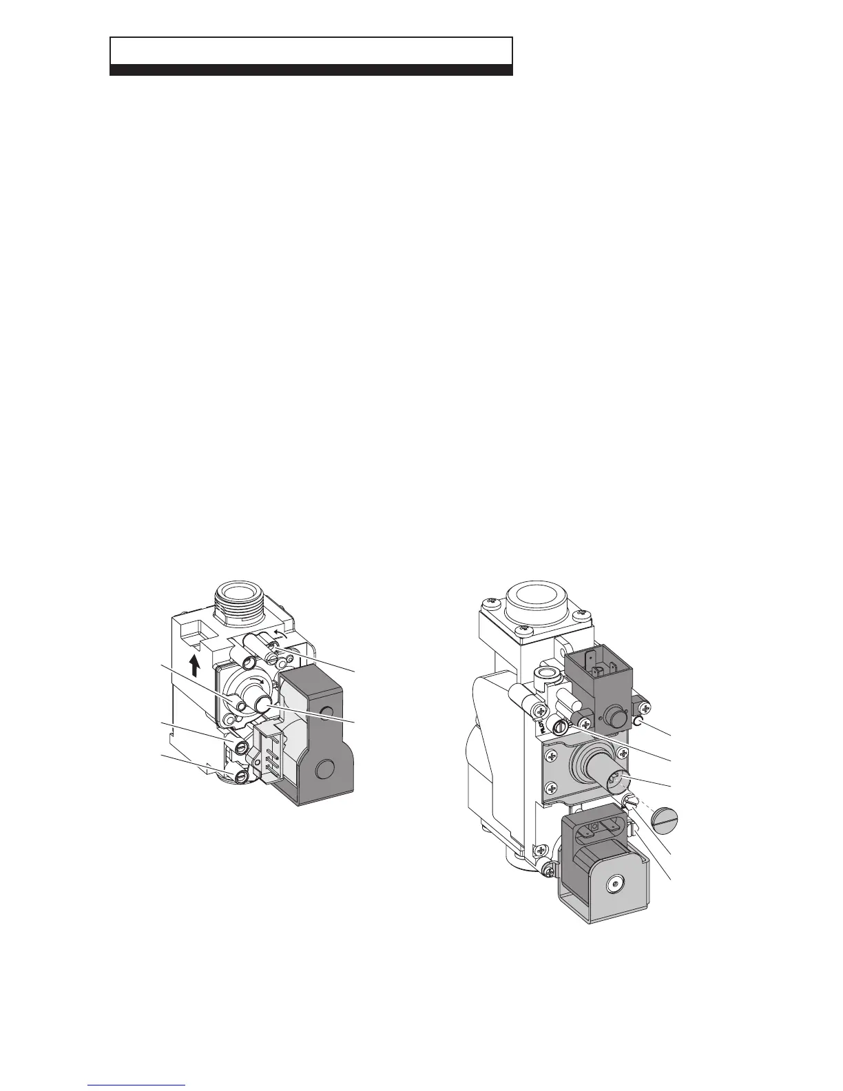
Fig. 5.1
Pro Tec 50, 70 gas valve Pro Tec 90, 115 gas valve
+
+
P1
2 (P3)
1
3
4
1
2 (P3)
3
4
P1
1 - Inlet gas pressure point
2 - Outlet gas pressure point
3 - Off/Set adjustment screw (minimum)
4 - Outlet ow regulator (maximum)