31
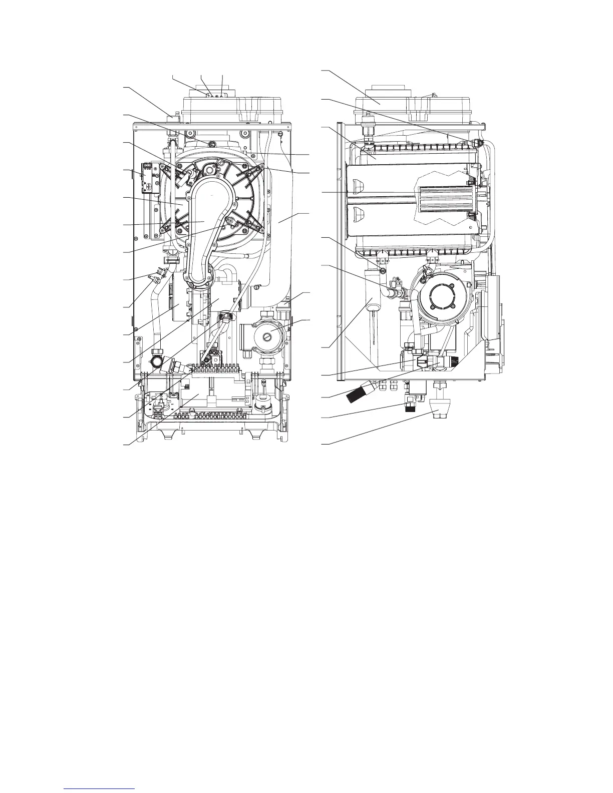
Alpha Pro Tec - Routine Servicing
Fig. 6.4 Pro Tec 50
1 PCB
2 Gas valve
3 Injector
4 Venturi housing
5 Fan
6 System ow NTC
7 Overheat thermostat
8 Flame detection electrode
9 Manifold cover
10 Combustion chamber front cover
11 Ignition unit
12 Ignition electrode
13 Flue sensor
14 Automatic air vent
15 Test points (air A) - (ue F)
16 Flue hood manifold
17 Manual air vent
18 Condensing heat exchanger
19 Heat exchanger thermal fuse
20 Overheat thermostat (manual reset)
21 Burner
22 Air intake pipe
23 System return NTC
24 Primary ow sensor
25 Automatic air vent
26 Pump
27 Condensate trap
28 Flow manifold
29 Safety valve 4 bar
30 Gas cock
31 Tundish
Front Left side