6
* Maximum Flue Lengths (includes rst bend onto boiler ue connection for horizontal installations)
* Max. ue length 80/125 concentric (room sealed) m
* Max. ue length 80 single pipe (B23 open ue) m
Flue system (optional) Concentric ue mm
Hole in wall required mm
Flue system (as supplied) Open ue mm
Hole in wall required mm
11
28
80/125
127
80
100
8
14
80/125
127
80
100
5
8.5
80/125
127
80
100
14.5
30
80/125
127
80
100
Pro Tec 115Pro Tec 50 Pro Tec 70 Pro Tec 90
Open ue - Maximum horizontal or vertical ue with single 80 mm dia. according to Table above
90° bend is equivalent to 2.1 m of ue length
45° bend is equivalent to 1.3 m of ue length
Vertical terminal is equivalent to 2 m of ue length
Concentric ue - Maximum horizontal ue or vertical ue according to Table above
90° bend is equivalent to 1.9 m of ue length
45° bend is equivalent to 1.4 m of ue length
Vertical terminal is equivalent to 2 m of ue length
Notes: 1. Ensure all ues slope downwards towards the boiler by a minimum of 25 to 30 mm per metre of ue.
2. It is recommended that horizontal and vertical ue assemblies should be supported approximately every 1.5 m with
access provided to the joints.
3. These dimensions only apply for ue parts supplied by Alpha.
Cascade ue options are also available, please contact Alpha for further details.
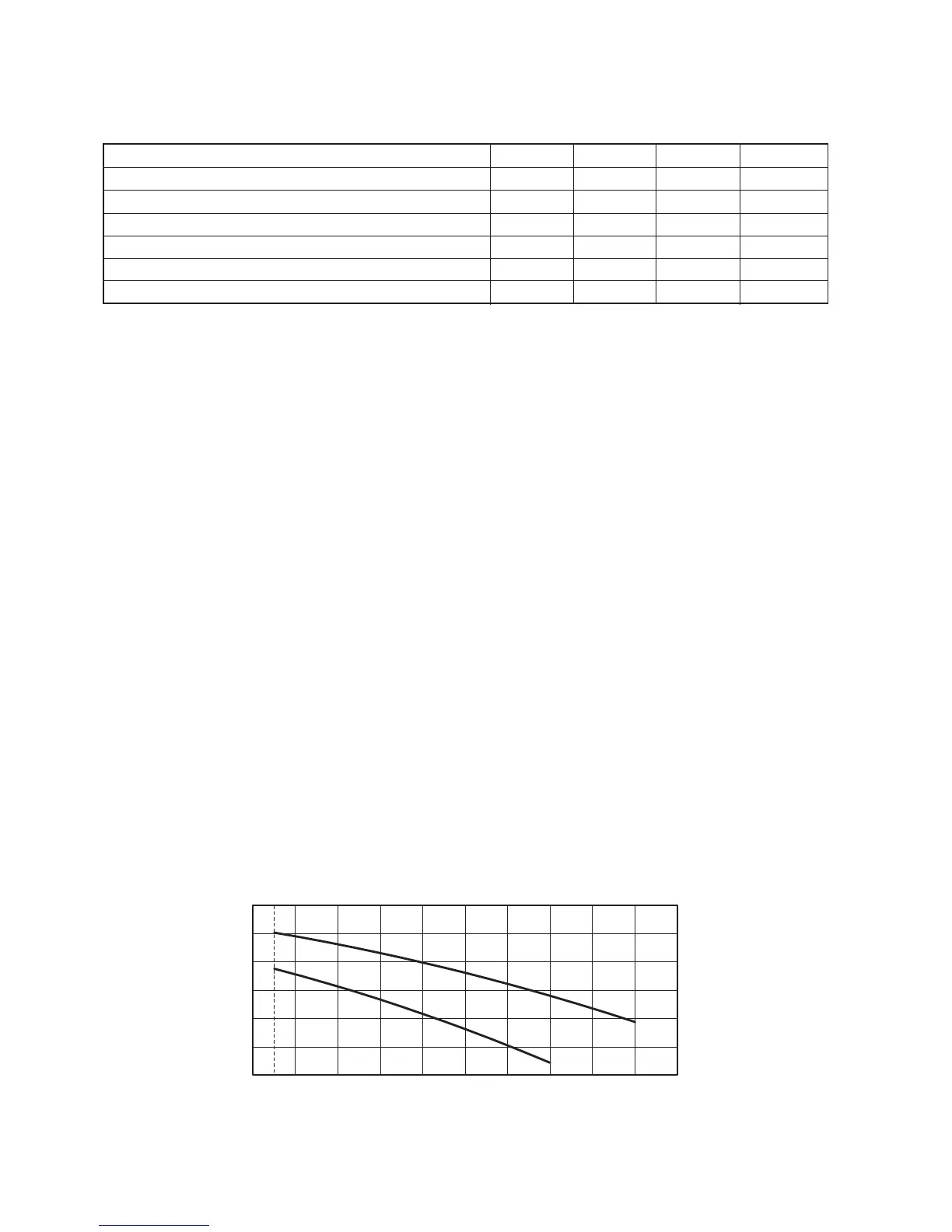
2.4 FLUE DATA
2.5 AVAILABLE PUMP HEAD
Fig. 2.1
The Pro Tec boilers are tted with a 3 speed pump. The boiler does not operate correctly with the pump set at the slowest
speed. To ensure optimal boiler operation, especially in the case of new systems it is recommended that the pump is set to
maximum speed.
The following graphs indicate the pump head and ow rates available at the maximum speed setting (A) and the middle
speed setting (B).
Pump release: If, after a prolonged period of inactivity, the pump is sticking, unscrew the front cap and turn the motor shaft
using a at bladed screwdriver. Take great care during this operation to avoid damage to the motor.
For larger systems an additional external pump can be tted and controlled by the boiler using a relay switch. See Fig. 2.5.
A
B
1.0
2.0
3.0
4.0
5.0
6.0
0
Flow rate (l/h)
Head
(m water)
800 850 1000 1100 1200 1300 1400 1500 1600 1700 1800900
Pro Tec 50
Alpha Pro Tec - Data