9
Alpha Pro Tec - Data
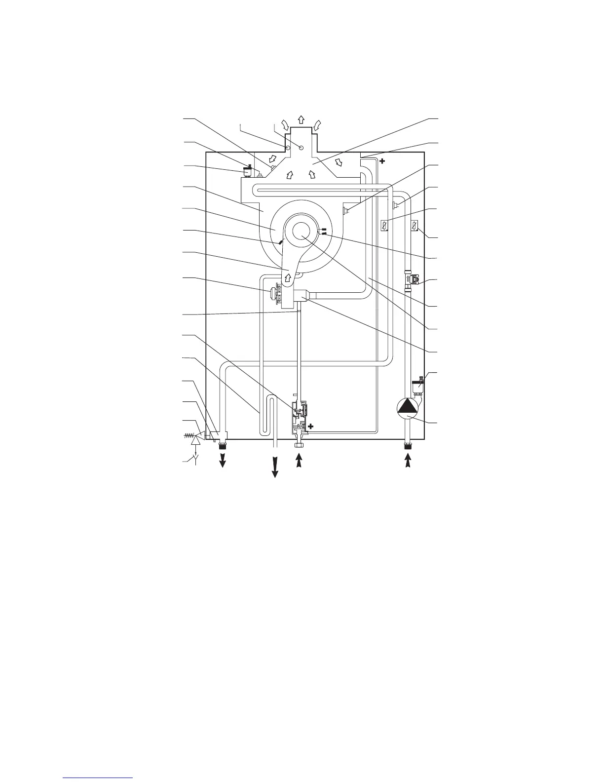
1 Tundish
2 Safety valve (4 bar)
3 Drain point
4 Flow manifold
5 Condensate trap
6 Gas valve
7 Injector
8 Fan
9 Manifold cover
10 Ignition electrode
11 Combustion chamber cover
12 Heat exchanger
13 Heat exchanger automatic air vent
14 Flue sensor
15 Thermofuse
Fig. 2.6
16 Air sampling point
17 Flue sampling point
18 Flue hood
19 Venturi positive point (P2)
20 Overheat thermostat (manual reset)
21 Overheat thermostat
22 Primary ow temperature sensor
23 Primary return temperature sensor
24 Flame sensing electrode
25 Primary ow sensor
26 Air inlet pipe
27 Burner
28 Venturi
29 Automatic air vent
30 Pump
2.7 BOILER SCHEMATIC
Pro Tec 50
15
14
13
12
11
10
9
8
7
6
5
4
3
2
1
16 17 18
19
20
21
22
23
24
25
26
27
28
29
30
Return
Gas
Flow
Condensate
discharge
(P3)