Do you have a question about the Alpine 3002 and is the answer not in the manual?
Details power output, distortion, frequency response, and SNR.
Defines input sensitivity, frequency range, and load impedance.
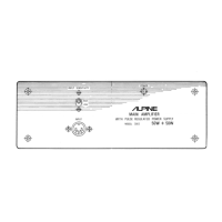
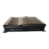
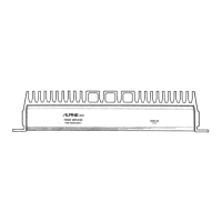
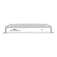
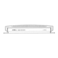
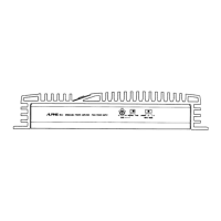
Provides physical measurements and weight of the unit.
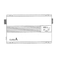
Identifies input sensitivity switch, indicator, and DIN jack.
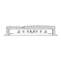
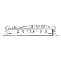
Identifies speaker, input, power, ground, and signal leads.
Locates fuse holders for 4A and 20A fuses.
Step-by-step guide to removing the front panel.
Instructions for removing top and bottom covers.
Procedures for removing rear panel, relay, and amplifier PCBs.
Procedure to set the amplifier's output voltage.
Procedure to adjust the amplifier's cut-off circuit.
Identifies variable resistors for adjustments.
Shows layouts of relay and main PCBs.
Component layout for the amplifier board's top side.
Component layout for the amplifier board's bottom side.
Key information regarding component values and types.
Lists components for the main circuit board assembly.
Lists all diode components used in the unit.
Lists transformers, filters, and connectors.
Lists all capacitor components with their values.
Lists all resistor components with their values.
Continues the list of resistor components.
Lists components for the relay circuit board.
Lists ICs, LEDs, and fuses.
Lists general hardware and assembly components.
Lists parts related to packaging and manuals.
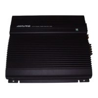
This document serves as a service manual for the Alpine Main Amplifier, Model 3002, which features a Pulse Regulated Power Supply.
The Alpine Main Amplifier, Model 3002, is designed to amplify audio signals, providing a robust power output for speaker systems. Its core functionality revolves around a pulse-regulated power supply, which is a key feature for efficient and stable power delivery. The amplifier includes input sensitivity controls for both high and low impedance sources, allowing for flexibility in connecting various audio devices. It also incorporates a power indicator to show operational status. The amplifier is equipped with multiple input and output leads for connecting speakers, input sources, and power, including dedicated leads for use as a power booster.
The amplifier operates on a power source of 14V D.C., with an allowable range of 11 to 16V. Power Output: More than 43W per channel into a 4-ohm load, across a frequency range of 30 Hz to 20 kHz, with a Total Harmonic Distortion (T.H.D.) of 0.2%. Distortion (T.H.D.): Less than 0.2% (4 ohm, 30 Hz to 20 kHz, 43W x 2). IM Distortion: 0.2% (4 ohm, 500mW to 43W IHF, Din Input). Frequency Response:
The internal components include various transistors (2SC1913, 2SC1826, 2SA912, 2SA921, 2SC2722), diodes (SR1K-4, 1SR-17-200, BZ-050, S-3V-20, CTU-22S, WZ-210), capacitors (ceramic, mylar, electrolytic), resistors (carbon film, metal film), transformers (Driver, Power), filters (Line, Choke), speaker coils, and integrated circuits (SI-1340H). It also features fuses for protection (20A and 4A).
The amplifier provides a straightforward interface for users. Input Sensitivity Switch Lever (SW001): Allows selection between HIGH and LOW input sensitivity, accommodating different source signal levels. Power Indicator (D001): A red LED that illuminates to indicate that the amplifier is powered on. 5P INPUT Din Jack (E001): A standard DIN connector for audio input. Speaker Output Leads (J001): Clearly labeled leads for connecting right (Gray) and left (Green) speakers. Input Leads (J003, J004): Separate gray and green leads for right and left input, respectively, specifically for use when the device functions as a power booster. Power Lead (J006): A yellow lead for connecting to the battery, providing the main power supply. Ground Lead (J007): A black lead for grounding the amplifier. Ignition Switch Lead (J008): A red/white lead for connection to the ignition switch, likely for remote power control. +B Lead (J009): A red lead providing +B voltage for a tuner/deck or radio player. Ground/Input Lead (J005): A black lead for ground or input when used as a power booster. Fuse Holders (4A and 20A): External fuse holders for easy access and replacement, ensuring protection against overcurrent.
The manual provides detailed instructions for disassembly and adjustment, crucial for maintenance and repair. Disassembly Instructions:
Adjustment Procedures:
Parts List: A comprehensive list of all components, including their symbol number, part number, and description, is provided for easy identification and replacement. This includes transistors, diodes, transformers, filters, jacks, resistors, capacitors, ICs, and fuses. Printed Circuit Board Layouts: Detailed top and bottom views of the Relay P.C. Board and Amplifier P.C. Board are included, showing component placement and test points (TP1, TP2, TP3, TP4), which are essential for troubleshooting and adjustments. Wiring Diagram: A clear diagram illustrates the connections between different components and external leads, aiding in understanding the electrical flow and diagnosing connectivity issues. Schematic Diagram: A full schematic diagram provides a detailed view of the amplifier's internal circuitry, including component values and interconnections, which is indispensable for advanced repairs and modifications. Semi-Conductor Lead Identifications: Diagrams showing the lead configurations for various transistors (2SA912, 2SA913, 2SA921, 2SC1913, 2SC2722, 2SC1826) and ICs (SI-1340H) are provided, ensuring correct installation and testing. Exploded View: An exploded diagram of the amplifier shows the assembly order and location of all mechanical and electrical parts, simplifying reassembly and identification of components. General Assembly Parts List: A list of all parts required for the overall assembly, including screws, washers, brackets, and panels, is provided. Packing Assembly Parts: Details on the packaging components, such as mounting brackets, polyethylene sacks, and the owner's manual, are also included.