18
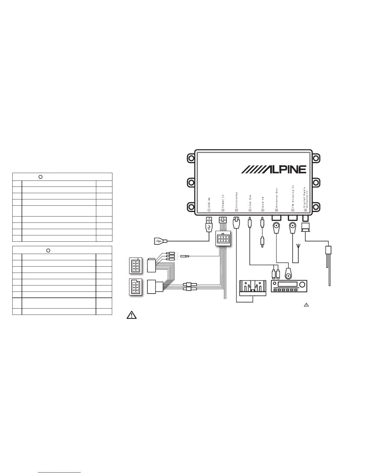
Connections and System Wiring
Diagram
A
EZi-DAB power connector pins
Pin Function Colour
1 Nav_Tel_Audio+ Purple
2 Nav_Phone_Mute Grey
3 Cabin illumination Brown
4 12V Permanent battery supply (with series fuse
holder)
Yellow
5 Nav_Tel_Audio_GND Pink
6 12V Switched ignition (with series fuse holder) Red
7 Car mute (with crimp) Orange
8 Ground Black
B
ISO connector pins
Pin Function Colour
1 Mute 1 (with crimp) White
2 Mute 2 (with crimp) Orange
3 Mute 3 (with crimp) Blue
4 12V Switched ignition (with series fuse holder)
* Red
5 Not used Green
6 Cabin illumination Brown
7 12V Permanted battery supply (with series fuse
holder)
*
Yellow
8 Ground Black
2
4
6
8
2
1
4
3
6
5
8
7
1
3
5
7
1
5
2
6
3
7
4
8
USB extension cable
(supplied)
AUX IN cable
(3.5mm supplied)
Existing vehicle FM
antenna
†
FM loop-through
cable (supplied)
†
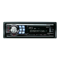
Head Unit
Head Unit AUX IN connection
cable (3.5mm to dual phono
or 3.5mm)
†
EZi-DAB controller bracket (supplied)
Power loom
(supplied)
Fuse holders for
permanent 12V and
switched 12V.*
Mute
* On some vehicles switched and permanent live connections may be reversed.
Open the fuse holders and swap the connections round if required.
†
If connected to Head Unit AUX IN then FM antenna connections to EZi-DAB are not required.
Optional antenna (e.g. KAE-220DA)
or any active (powered) DAB antenna
with 5V phantom feed and SMB (f)
connector
Please make sure ONLY to connect
a dedicated 5V phantom supplied
antenna. Failure to do so may result
in the device becoming defect.