1
EspañolFrançais
English
R
•OWNER'S MANUAL
Please read this manual to maximize your enjoyment of the outstanding
performance and feature capabilities of the equipment, then retain the
manual for future reference.
•MODE D'EMPLOI
Veuillez lire ce mode d'emploi pour tirer pleinement profit des
excellentes performances et fonctions de cet appareil, et conservez-le
pour toute référence future.
•MANUAL DE OPERACION
Lea este manual, por favor, para disfrutar al máximo de las
excepcionales prestaciones y posibilidades funcionales que ofrece el
equipo, luego guarde el manual para usarlo como referencia en el futuro.
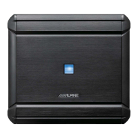
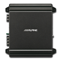
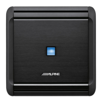
MRV-F450
5/4/3 CHANNEL POWER AMPLIFIER
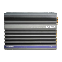
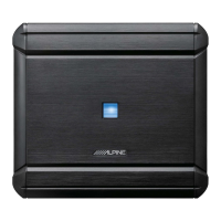
MRV-F540/MRV-F340
4/3/2 CHANNEL POWER AMPLIFIER
CONTENTS
WARNING............................................................... 2
CAUTION ................................................................ 3
INSTALLATION ....................................................... 4
CONNECTIONS ....................................................... 6
CONNECTIONS CHECK LIST................................. 10
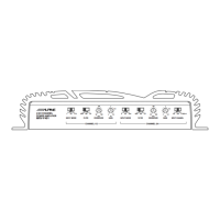
SWITCH SETTINGS .............................................. 12
SYSTEM DIAGRAMS ............................................ 15
SPECIFICATIONS .................................................. 19
ACCESSORIES
• End Cover........................................................... 1
• Terminal Cover ................................................... 1
• Bracket ............................................................... 2
• Hexagon Wrench (M3) ....................................... 1
• Hexagon Wrench (M4) ....................................... 1
• Self-Tapping Screw ............................................ 4
• Machine Screw................................................... 4
• Hexagon Screw (M3) ......................................... 2
• Hexagon Screw (M4) ......................................... 3
• Double Face Tape ........................................ 1 SET
• Cushion ....................................................... 1 SET
• Insulation Tube (for Power Supply/
for Speaker Output).................................... 1 SET
• Rubber pipe........................................................ 1
• Speaker Input Connector (MRV-F340 only)........ 1
TABLE DES MATIERES
AVERTISSEMENT ...................................................... 2
ATTENTION................................................................ 3
INSTALLATION .......................................................... 4
CONNEXIONS ............................................................ 6
LISTE DE VERIFICATION DES CONNEXIONS........... 10
REGLAGES DE COMMUTATEUR .............................. 12
DIAGRAMMES DU SYSTEME .................................. 15
SPECIFICATIONS ..................................................... 19
ACCESSOIRES
• Couvercle d’achèvement........................................ 1
• Couvercle cache-bornes ........................................ 1
• Support ................................................................. 2
• Clé hexagonale (M3) ............................................. 1
• Clé hexagonale (M4) ............................................. 1
• Vis autotaraudeuse................................................ 4
• Vis à métaux.......................................................... 4
• Vis à six pans (M3) ............................................... 2
• Vis à six pans (M4) ............................................... 3
• Ruban adhésif double face ............................. 1 JEU
• Coussin .......................................................... 1 JEU
• Tube d’isolation (pour alimentation/
pour la sortie de haut-parleur)......................... 1 JEU
• Tube en caoutchouc .............................................. 1
• Connecteur d’entrée de haut-parleur
(uniquement MRV-F340)....................................... 1
INDICE
ADVERTENCIA........................................................ 2
PRUDENCIA ........................................................... 3
INSTALACION ......................................................... 4
CONEXIONES ......................................................... 6
LISTA DE VERIFICACION DE CONEXIONES .......... 10
AJUSTES DEL INTERRUPTOR.............................. 12
DIAGRAMAS DEL SISTEMA ................................. 15
ESPECIFICACIONES ............................................. 19
ACCESORIOS
• Cubierta de acabado ........................................... 1
• Cubierta de terminales ....................................... 1
• Soporte .............................................................. 2
• Llave hexagonal (M3) ......................................... 1
• Llave hexagonal (M4) ......................................... 1
• Tornillo autorroscante ........................................ 4
• Tornillo para metales .......................................... 4
• Tornillo hexagonal (M3) ..................................... 2
• Tornillo hexagonal (M4) ..................................... 3
• Cinta de doble cara................................. 1 JUEGO
• Almohadilla ............................................ 1 JUEGO
• Tubo de aislamiento (para la alimentación/
para la salida de altavoz) ........................ 1 JUEGO
• Tubo de caucho .................................................. 1
• Conector de entrada del altavoz
(MRV-F340 solamente) ...................................... 1
EspañolFrançais
English