Do you have a question about the Alpine MRV-V500 and is the answer not in the manual?
Read manual, follow instructions for safe operation.
Do not operate functions that take attention away from driving.
Maintain volume to hear external sounds and prevent hearing damage.
Do not disassemble or alter the unit to prevent hazards.
Use correct voltage, fuses, wiring, and installation practices.
Do not use brake/steering system parts for ground connections.
Keep small objects like batteries out of reach of children.
Stop using the product immediately if a problem appears.
Have wiring and installation performed by experts for safety.
Use specified accessory parts and install them securely.
Arrange wiring to prevent crimping or pinching by sharp edges.
Avoid installing in locations with high moisture or dust.
Amplifier tested to comply with FCC Class B limits for radio frequency energy.
Record serial number, installation date, technician, and place of purchase.
Information for European and other country customers regarding warranty.
Lists included items like screws, terminal cover, and connectors.
Mount amplifier for free air circulation due to heat production.
Use amplifier as template, mark holes, drill, and secure with screws.
Connect ground lead securely to bare metal for noise elimination.
Attach covers after connections for improved unit appearance.
Connect battery lead with in-line fuse to positive terminal, not fuse block.
Route leads away from harness, keep power leads separate, connect ground securely.
Insert terminal type; ensure correct polarity with other speakers.
Input is stereo, output is monaural; polarity may be reversed for bass.
Connect left positive and right negative to speaker terminals for bridged mode.
MRV-V500 requires two 30A fuses.
Connect to battery positive terminal.
Use 60 amp fuse and 4 AWG/21 mm² wire for battery lead.
Use 4 AWG/21mm² wire for secure chassis ground connection.
Connect to head unit's remote turn-on or power antenna lead.
For head units without preamp outputs; connects to speaker output leads.
Connect to head unit line out using RCA extension cables.
Optional control to adjust output level remotely.
Identifies connectors for front, rear, and subwoofer speakers.
Recommendations for power/ground cable gauge and distribution blocks.
Cautions on checking wire size and making connections.
Strip wire ends to 7-10 mm for proper connection.
Tighten hexagon hole screw with wrench to secure lead.
Use included screws, connect battery last, do not use cabling to carry unit.
Verify head unit remote turn-on lead availability or alternative connection methods.
Connect to ignition tap via a 3A fuse if no remote lead is available.
Install SPST switch for manual turn-on/off control.
Select OFF for full range or ON for tweeter/midrange systems.
Select 2-channel or 4-channel input mode for signal distribution.
Adjust amplifier gain to match head unit output for optimal sound.
Adjust crossover frequency between 50 and 400 Hz.
Add 50 Hz bass boost up to +12 dB.
Describes indicator colors (Blue, Red) and their meanings for normal, overheating, or abnormal conditions.
Illustrates 4 Speaker + 1 Subwoofer system with 5-channel input.
Details speaker level input connection, Remote Sensing, and input mixing.
Diagram for 4 speaker + 1 subwoofer system with 4-channel input.
Diagram for 4 speaker + 1 subwoofer system with 2-channel input.
Shows how to bridge channels for a 2 speaker + 1 subwoofer setup.
Provides tips and diagrams for proper bridged amplifier connections.
Details power output, THD+N, S/N ratio, and frequency response.
Covers input select, sensitivity, crossover, equalizer, impedance, dimensions, and weight.
Details what is covered, duration, and who is protected by the warranty.
Lists items and conditions not covered by the warranty.
Steps for returning a product for warranty repair or replacement.
Discusses implied warranties and state/provincial law relation.
Warranty validity requires installation by an authorized center in Canada.
Provides phone numbers and website for customer service.
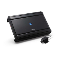
| Product color | Black |
|---|---|
| Amplifier class | D |
| Signal-to-Noise Ratio (SNR) | 98 dB |
| Number of amplifier channels | 5 channels |