45
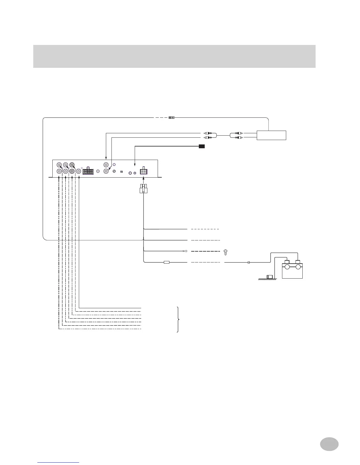
TyPICAL SySTEm DIAGRAmS
(L)
(R)
(L)
(R)
(+)
(-)
FR
ONT 1
FR
RCA OUTPUT AUTO RANGING
INPUT
INPUT
ONT 2 REAR
SUBWOOFER
MIC
CLIP
AUX OFF ON
INPUT LEVELAUX
L1 L2 R1 R2 S
AUX
PRIMARY
SOURCE
WIRED
REMOTE
INPUT
REMOTE
IR INPUT
PO WER SUPPLY
White/Brown
Blue/White
Black
Yellow
Remote Control Cable
Blue/White
Remote ON Cable
Blue/White
*Remote OUT Cable
Remote OUT Cable
Ground Cable
Battery Power Cable
Not used in this system
IR Sensor
To External Alpine Remote ON Cable
Connect to a metal part of chassis
body with a screw
To External Amplier
Subwoofer Output
Rear Output (L)
Rear Output (R)
Front 2 Output (L)
Front 2 Output (R)
Front 1 Output (L)
Front 1 Output (R)
6 CH System with Subwoofer
* AUX Primary Source switch must be ON for this system
- +
Batt ery
AFT Head Unit
RCA Connection Cable
To external amplifier remote on cable
Typical Aftermarket System