EasyManua.ls Logo

Alpine TDA7556R - User Manual

Alpine TDA7556R
90 pages
Print Icon
To Next Page IconTo Next Page
Loading...
/U07AALP
INE.
.
SERVICE
MANUAL
FM/MW/LW/RDS
Cassette
Receiver
CyYD
Shmuttie
Controller
@
The
model
described
in
this
manual
is
developed
from
Model
TDM-7531R/TDM-
7532R/TDM-7535R.
For
information
that
is
not
mentioned
in
this
service
manual,
refer
to
the
Service
Manual
¢
TDM-7531R/TDM-7532R/TDM-7535R
(Part
No.
68E21961S01).
@
For
the
cassette
deck
mechanism
parts
(GR75S120/130)
of
this
model,
refer
to
the
Service
Manual
e
GR-S
Series
(Part
No.
68E23241S01).
‘i_CD
Shuttle
control
7]
2220
4
Ty
ICM.
eee
(TDA-7556R)
nA
ZS
Sok
ADA
SZoS
SIR
TOAS7/
S828)
71D
Ar7/7SSO0R}
Question and Answer IconNeed help?

Do you have a question about the Alpine TDA7556R and is the answer not in the manual?

Alpine TDA7556R Specifications

General IconGeneral
CategoryCar Receiver
TunerAM/FM
BluetoothYes
USB PortYes
Aux InputYes
Display TypeLCD
Channels4
Built-in AmplifierYes
CD PlayerNo
MP3 PlaybackYes
WMA PlaybackYes
Remote ControlYes
Detachable FaceplateYes
EQ SettingsYes

Summary

FM;MW;LW;RDS Cassette Receiver

CD Shuttle Controller

Details the functionality and features of the CD shuttle controller.

Specifications

Tape Player Specifications

Technical specifications for the tape player section.

General Specifications

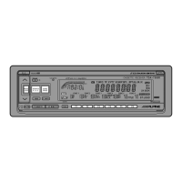
Overall technical specifications for the unit.

Packing Assembly Parts List

Packing Method View

Visual guide showing how parts are packed.

Adjustment Procedures

FM Section Adjustments

Procedures for adjusting the FM tuner circuit.

IF Adjustment

Procedure to adjust the Intermediate Frequency.

Signal Meter Adjustment

Procedure to adjust the signal meter calibration.

Tape Player Adjustments

Procedures for adjusting tape player functions like azimuth and speed.

Adjustment Locations

Description of IC Terminal

IC501 Terminal Descriptions

Details the function of each pin for IC501.

IC502 Terminal Descriptions

Details the function of each pin for IC502.

LCD Display

Block Diagram

Overall System Block Diagram

Visual representation of the system's interconnected components.

Parts Layout and Wiring Diagram (1;4)

Parts Layout and Wiring Diagram (2;4)

Parts Layout and Wiring Diagram (3;4)

Parts Layout and Wiring Diagram (4;4)

Schematic Diagram (1;6)

Main P.C. Board Schematic

Circuit diagram for the main printed circuit board.

Schematic Diagram (2;6)

Schematic Diagram (3;6)

Schematic Diagram (4;6)

Schematic Diagram (5;6)

Schematic Diagram (6;6)

Electrical Parts List

Main P.C. Board Components

List of electronic components for the main P.C. board.

Transistor Components

List of transistors used in the unit.

Exploded View (Cabinet)

Disassembly Instructions

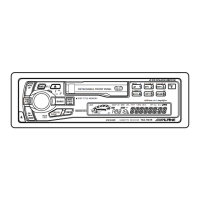
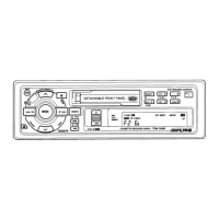
Step-by-step guide for disassembling the unit.

Cabinet Assembly Parts List

Semi-Conductor Lead Identifications

Cassette Deck Mechanism

Basic Operation of GR-S Mechanism

Explains the fundamental operating principles of the GR-S mechanism.

Disassembly, Assembly and Replacement of Function Parts

Procedures for disassembling and reassembling mechanism parts.

Exploded View (Cassette Deck Mechanism)

Diagram showing the assembly of cassette deck mechanism parts.

Cassette Deck Mechanism Assembly Parts List

List of parts for the cassette deck mechanism assembly.

Loading Operation

Play Operation

Explains the steps involved in the play mode operation.

PROG Operation

Details the operation for programming tracks.

FF;REW (QUE;REVIEW)

EJECT Operation

Procedure for ejecting the cassette.

Operations of MODE SW and PAUSE SW

Mechanism Basic Operation Timing Chart

Disassembly, Assembly and Replacement of Functional Parts

Bottom Cover Disassembly and Assembly

Procedure for removing and reattaching the bottom cover.

Bottom Cover Mounting Parts Replacement

Steps for replacing gears and photo sensor.

Detector Switch Replacement

Procedure for replacing pause, metal, and mode detector switches.

Mounting Parts Replacement on Rear Chassis

Steps for replacing the belt.

Main Motor Replacement

Steps for replacing the main motor assembly.

Head Replacement

Procedure for replacing the playback head assembly.

Exploded View (Cassette Deck Mechanism)

Cassette Deck Mechanism Assembly Parts List

FM;MW;LW;RDS Cassette Receiver

CD Shuttle Controller

Details the functionality and features of the CD shuttle controller.

Specifications

Packing Assembly Parts List (Only Difference)

List of packing parts specific to TDA-7550R model.

Packing Method View

Visual guide showing how parts are packed.

Schematic Diagram (6;6)

Circuit diagram for the GR control P.C. board.

Electrical Parts List (Only Difference)

List of electrical parts specific to TDA-7550R model.

Packing Assembly Parts List

Packing Method View

Visual guide showing how parts are packed.

Parts Layout on P.C. Boards and Wiring Diagram (3;4)

Schematic Diagram (6;6)

Electrical Parts List

Cassette Deck Mechanism

Basic Operation of GR-S Mechanism

Explains the fundamental operating principles of the GR-S mechanism.

Disassembly, Assembly and Replacement of Function Parts

Procedures for disassembling and reassembling mechanism parts.

Exploded View (Cassette Deck Mechanism)

Diagram showing the assembly of cassette deck mechanism parts.

Cassette Deck Mechanism Assembly Parts List

List of parts for the cassette deck mechanism assembly.

Cassette Deck Mechanism Assembly Parts List

Exploded View (Cassette Deck Mechanism)

Cassette Deck Mechanism

Cassette Deck Mechanism Assembly Parts List

List of parts for the cassette deck mechanism assembly.

Exploded View (Cassette Deck Mechanism)

Diagram showing the assembly of cassette deck mechanism parts.

Basic Operation of GR-S Mechanism

Explains the fundamental operating principles of the GR-S mechanism.

Disassembly, Assembly and Replacement of Function Parts

Procedures for disassembling and reassembling mechanism parts.

Cassette Deck Mechanism Assembly Parts List

Exploded View (Cassette Deck Mechanism)

Related product manuals