positive and negative stripped wires into the spring clips marked LEFT
FRONT on the Subwoofer.
2. Insert the ends of the stripped wires from the RIGHT REAR Satellite
into the spring clip marked RIGHT REAR on the Subwoofer (dot-dash
design wire into red push button clip; plain wire into black push button
clip); repeat this procedure for the LEFT REAR Satellite, inserting the
stripped wires into the spring clips marked LEFT REAR on the
Subwoofer.
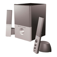
3. Connect the gray DIN plug from the System Controller unit into the
gray DIN jack marked CONTROLLER on the Subwoofer. Note that the
DIN plug has an arrow. The arrow should be face up for correct
insertion into the DIN jack on the Subwoofer.
4. Shut the computer system down using the manufacturer's
recommended procedures.
5. The 641 provides two inputs labeled FRONT and REAR, located on
the Subwoofer. Computer gaming sound cards have at least 2 outputs.
Most often, the outputs will be marked as front output, and rear output.
Some slightly different terminology may be used. However, the sound
card instructions will provide information so that you can determine what
outputs to use with a two input speaker system. Make the connections
using the two 6.5' (5 m) green and black cables with matching 3.5 mm
stereo plugs on each end. These cables are included with the 641
system.
6. Connect the power cord (at back of Subwoofer) to an AC Wall socket.
7. The unit is now ready to operate. Turn on the audio source device.
Note: Always turn on your audio source device before turning on your
Altec Lansing 641 Speaker System. If you turn on the speaker system
before turning on the audio source, you will hear a loud POP sound
when the audio device is turned on.
8. Turn on the Altec Lansing 641 Speaker System. See USE OF
CONTROLS below.
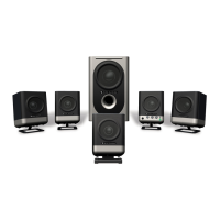
Stereo and Stereo x2 Setup:
There are two modes of operation for stereo input: Stereo and Stereo
x2. In Stereo mode, the Front Satellites as well as the Subwoofer are
operational. In Stereo x2 mode, both Front and Rear Satellites are
operational. The Front and Rear Satellites in the left channel will
perform as the stereo left channel and the Right Front and Rear
Satellites will be the stereo right channel.
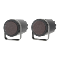
All Satellites will be connected to the back of the subwoofer. Each
Satellite has a cable composed of two stripped wires. The positive wire
is marked with a dot-dash design. The positive wire will be connected to
the appropriate spring clip opened by the red push button. The
negative wire will be connected to the appropriate spring clip opened by
the black push button.
1. Insert the ends of the stripped wires from the RIGHT FRONT Satellite
into the spring clips marked RIGHT FRONT on the Subwoofer (dot-dash
design wire into red push button clip; plain wire into black push button
clip); repeat this procedure for the LEFT FRONT Satellite, inserting the
positive and negative stripped wires into the spring clips marked LEFT
FRONT on the Subwoofer.
2. Insert the ends of the stripped wires from the RIGHT REAR Satellite
into the spring clip marked RIGHT REAR on the Subwoofer (dot-dash
design wire into red push button clip; plain wire into black push button
clip); repeat this procedure for the LEFT REAR Satellite, inserting the
stripped wires into the spring clip marked LEFT REAR on the
Subwoofer.
3. Connect the gray DIN plug from the System Controller unit into the
gray DIN jack marked CONTROLLER on the Subwoofer. Note that the
DIN plug has an arrow. The arrow should be face up for correct
insertion into the DIN jack on the Subwoofer.
4. Select one 6.5' (5 m) cable with lime green 3.5 mm stereo plugs on
each end and connect one end into the jack labeled FRONT on the
Subwoofer and the other to the 3.5 mm output jack on your audio
source.
5. Optional: Connect a second audio source to the Aux (Auxiliary) input
at the back of the Subwoofer. See How To Enhance Presentations With
Dialogue and Other Uses For The Aux (Auxiliary) Input below.
6. Connect the power cord (at back of Subwoofer) to an AC Wall socket.
7. The unit is now ready to operate. Turn on the audio source device.
Note: Always turn on your audio source device before turning on your
Altec Lansing 641 Speaker System. If you turn on the speaker system
before turning on the audio source, you will hear a loud POP sound
when the audio device is turned on.
8. Turn on the Altec Lansing 641 Speaker System. See USE OF
CONTROLS below.
FRONT INPUT AND
AUX (AUXILIARY) INPUT
Both inputs are equal. The Aux (Auxiliary) Input is located on the top
front of the Subwoofer. One input can be used for computer output and
the other as described in "How to Enhance Presentations with
Dialogue." Make connections as described above (CONNECTIONS).
Do not insert the AC power plug into the wall outlet before all
connections are made.
Headphones
Connect your headphones to the jack on the System Controller. When
headphones are connected, all speakers are muted.
USE OF CONTROLS
Power On/Off
The Power On/Off button is located on the System Controller. Press the
POWER button to turn on the speaker system. Push it again to turn the
unit off. One of the Mode LEDs will glow to show power is on.
Master Volume Control
Locate the rotary knob on the System Controller. The rotary knob acts
as the Master Volume control and has several functions. It operates as
a Master Volume control for the overall system when no other buttons
have been pushed. It is also used to individually adjust the levels of