52 • Section 6 — Operation
clear of the ground, the test weight hangs suspended
from the bottom of the platform for a specied period.
The test weight is then removed from the platform and
the lift may begin.
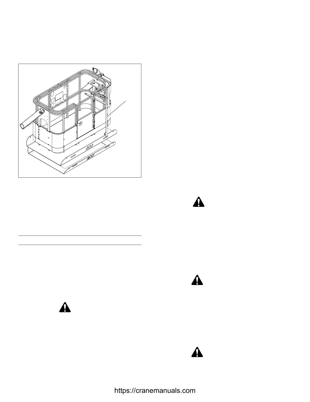
Figure 6.11 — Test Weight and Platform Mounted
It is permissible to lift the platform and test weight as one
from the deck. When the lift is complete, the platform
may be returned to the center of the test weight. With the
slings and shackles secure, the platform and test weight
may be lifted as one onto the deck of the machine and
secured for transport.
Jibs
All jibs will have a rated jib capacity placard mounted on
the jib bracket or jib boom. In some material handling jib
positions, the rated capacity of the winch will be greater
than the rated capacity of the jib.
Inspect the jib, jib mounting brackets, and pins prior to
installing the jib. Do not install the jib if any components
are damaged or missing.
WARNING
Death or serious injury can result from overloading
the jib. Do not exceed the values on the jib capacity
chart.
Death or serious injury can result from damaging
the jib. Refer to the capacity placards before using
a jib.
Before lifting a load with the jib, refer to Section 3 under
Capacity.
Installation and Stowing Procedure
The jib installation and stowing procedures are described
here and also on a placard on the unit.
To Install the Jib in the Working Position
1. Engage the PTO and properly set the outriggers.
2. Fully retract the boom and lower the boom tip until
it can be reached from the ground.
3. Remove the load block and auxiliary sheave from
the boom tip. Remove the anti-two-block switch and
chain clevis from the anti-two-block switch.
4. Remove the load line from the boom tip sheave (refer
to Figure 6.12). Replace the load line retaining pin.
5. Install the two pins from the pin stow bracket (pins
are stowed in brackets on each side of the jib) to
fasten the jib in place on the right side of the boom
tip. Install hairpin retainers in the pins.
6. Raise the boom to a horizontal position.
7. Fasten a tag line, approximately 15′ (4.57 m) long,
to the end of the jib.
DANGER
Death or serious injury will occur from uncontrolled
movement of the jib. Do not remove the jib stow pin
until the two pins have been installed on the right
side of the boom tip.
8. Remove the jib stow pin from the jib stow bracket.
9. Extend the boom approximately 15″ (38.10 cm) so
the jib stow bar is clear of the front jib stow bracket
(refer to Figure 6.12).
WARNING
Death or serious injury can occur from uncontrolled
movement of the jib. Maintain control of the jib when
swinging it into position.
10. Swing the jib into inline position with the tag line.
11. Install two pins from the pin stow bracket to fasten
the jib in place on the left side of the boom tip (refer
to Figure 6.12). Install hairpin retainers in these pins.
WARNING
Death or serious injury will result from a free falling
jib. Ensure that the jib pins and retaining pins are
properly installed.
Chain Path
https://cranemanuals.com


 To Next Page