DE1-SOC COMPUTER SYSTEM WITH NIOS II For Quartus II 15.0
pixel addresses. The defaults are n = 9, m = 8, B = 2, and A = 0. If the pixel buffer controller is changed to provide
different values of these fields, then the way in which pixel addresses are formed has to be modified accordingly. The
programming interface also includes a Resolution register, shown in Figure 29, that contains the X and Y resolution
of the pixel buffer(s).
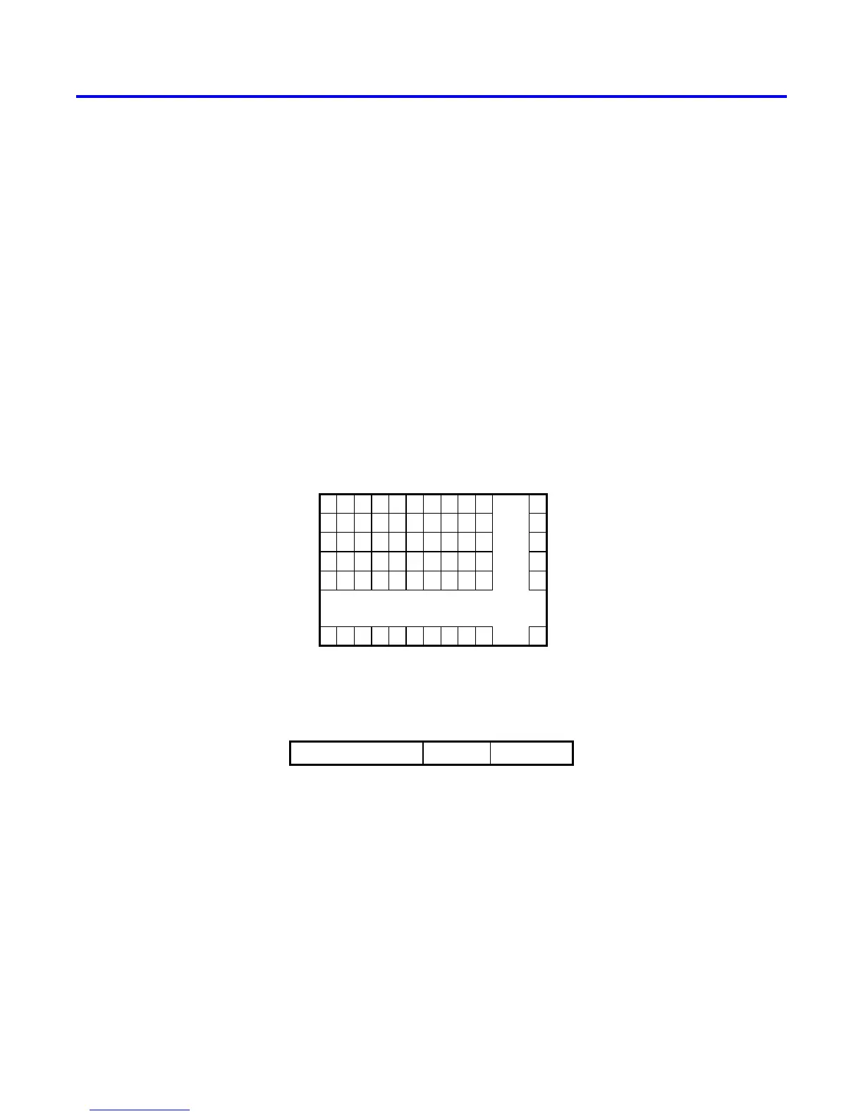
4.2.3 Character Buffer
The character buffer for the video-out port is stored in on-chip memory in the FPGA on the DE1-SoC board. As
illustrated in Figure 30a, the buffer provides a resolution of 80 × 60 characters, where each character occupies an
8 × 8 block of pixels on the VGA screen. Characters are stored in each of the locations shown in Figure 30a using
their ASCII codes; when these character codes are displayed on the VGA monitor, the character buffer automat-
ically generates the corresponding pattern of pixels for each character using a built-in font. Part b of Figure 30
shows that characters are addressed in the memory by using the combination of a base address, which has the value
(09000000)
16
, and an x,y offset. Using this scheme, the character at location 0,0 has the address (09000000)
16
, the
character 1,0 has the address base + (000000 0000001)
2
= (09000001)
16
, the character 0,1 has the address base +
(000001 0000000)
2
= (09000080)
16
, and the character at location 79,59 has the address base + (111011 1001111)
2
= (09001DCF)
16
.
790
. . .
123
. . .
. . .
. . .
. . .
0
1
2
. . .
59
31
. . .
0
. . .
712
0000100110000000000
613
xy
. . .
(a) Character buffer coordinates
(b) Character buffer addresses
Figure 30. Character buffer coordinates and addresses.
4.2.4 Using the Video-out Port with C code
A fragment of C code that uses the pixel and character buffers is shown in Figure 31. The first for loop in the figure
draws a rectangle in the pixel buffer using the color pixel_color. The rectangle is drawn using the coordinates x
1
, y
1
and x
2
, y
2
. The second while loop in the figure writes a null-terminated character string pointed to by the variable
text_ptr into the character buffer at the coordinates x, y. The code in Figure 31 is included in the sample program
Altera Corporation - University Program
2015
35
 Loading...


