DE1-SOC COMPUTER SYSTEM WITH NIOS II For Quartus II 15.0
012
0xFF20306C
Address
0xFF203070
Control
Edge-detection
EN
0
E
Unused
Unused
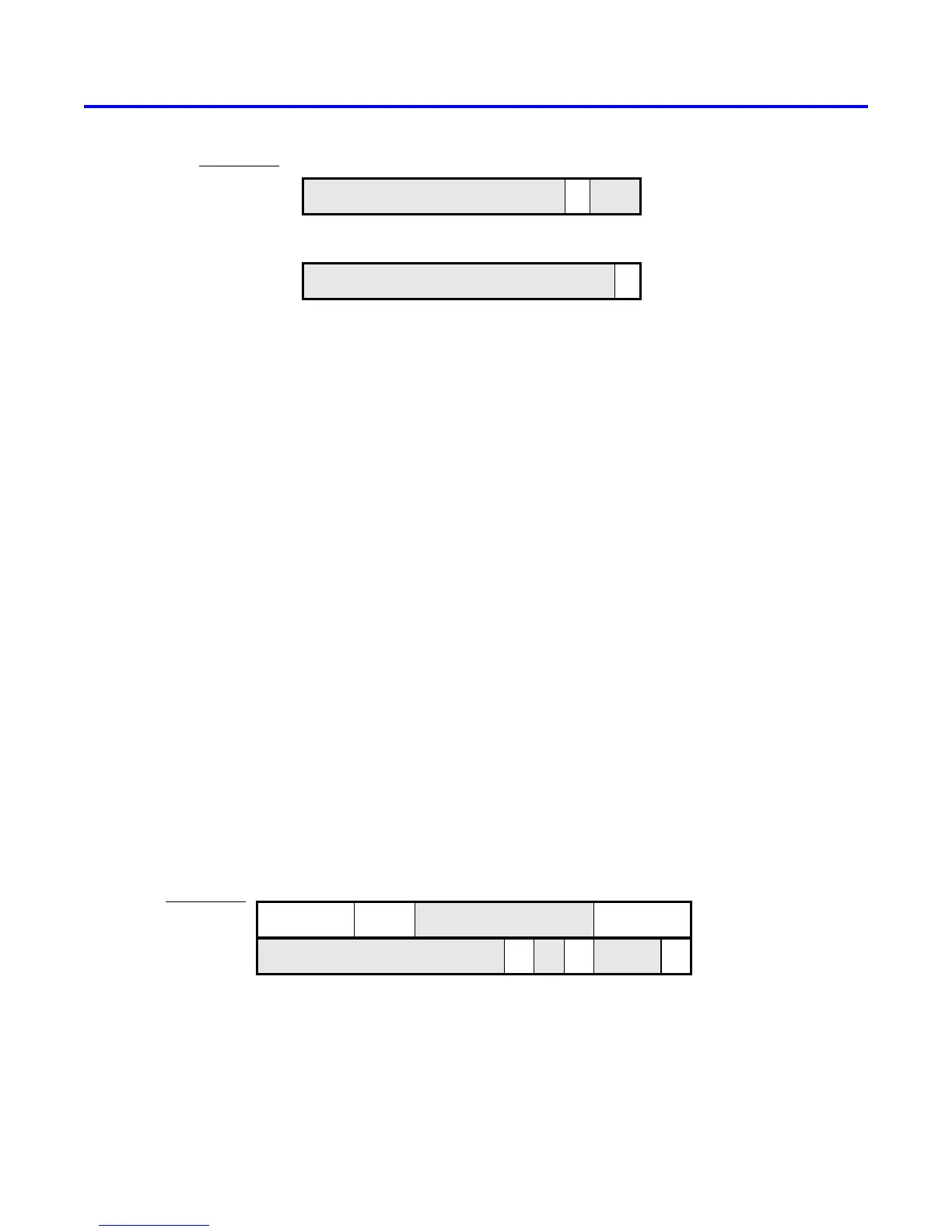
Figure 32. The video-in port programming interface.
4.4 Audio/Video Configuration Module
The audio/video configuration module controls settings that affect the operation of both the audio port and the video-
out port. The audio/video configuration module automatically configures and initializes both of these ports whenever
the DE1-SoC Computer is reset. For typical use of the DE1-SoC Computer it is not necessary to modify any of these
default settings. In the case that changes to these settings are needed, the reader should refer to the audio/video
configuration module’s online documentation, which is available from Altera’s University Program web site.
4.5 PS/2 Port
The DE1-SoC Computer includes two PS/2 ports that can be connected to a standard PS/2 keyboard or mouse. The
port includes a 256-byte FIFO that stores data received from a PS/2 device. The programming interface for the PS/2
port consists of two registers, as illustrated in Figure 33. The PS2_Data register is both readable and writable. When
bit 15, RVALID, is 1, reading from this register provides the data at the head of the FIFO in the Data field, and
the number of entries in the FIFO (including this read) in the RAVAIL field. When RVALID is 1, reading from the
PS2_Data register decrements this field by 1. Writing to the PS2_Data register can be used to send a command in
the Data field to the PS/2 device.
The PS2_Control register can be used to enable interrupts from the PS/2 port by setting the RE field to the value 1.
When this field is set, then the PS/2 port generates an interrupt when RAVAIL > 0. While the interrupt is pending
the field RI will be set to 1, and it can be cleared by emptying the PS/2 port FIFO. The CE field in the PS2_Control
register is used to indicate that an error occurred when sending a command to a PS/2 device.
Address
01531
. . .
0xFF200100
0xFF200104
. . .
Unused
RE
1
DataRAVAIL
16
PS2_Data
RI
. . .
89
CE
710
PS2_Control
RVALID
Figure 33. PS/2 port registers.
A fragment of C code that uses the PS/2 port is given in Figure 34. This code reads the content of the Data register,
and saves data when it is available. If the code is used continually in a loop, then it stores the last three bytes of data
Altera Corporation - University Program
2015
37
 Loading...


