Figure 2-2 tPad PCB and component diagram (bottom view)
2
2
.
.
2
2
B
B
l
l
o
o
c
c
k
k
D
D
i
i
a
a
g
g
r
r
a
a
m
m
o
o
f
f
t
t
h
h
e
e
t
t
P
P
a
a
d
d
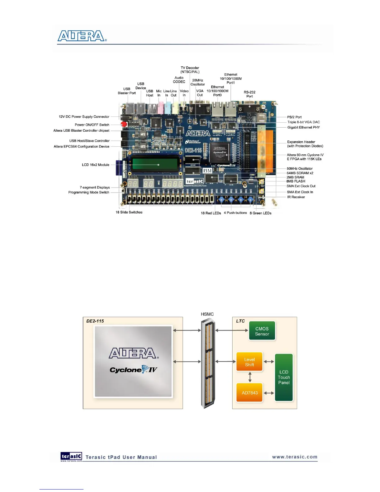
Figure 2-3 gives the block diagram of the tPad board. To provide maximum flexibility for the user,
all connections are made through the Cyclone IV E FPGA device. Thus, the user can configure the
FPGA to implement any system design.
Figure 2-3 Block Diagram of tPad
 Loading...