-+10
8
MAIN MIX
LEVEL
PHANTOM
POWER
2TK TO
MIX
AUX RTN 1
AUX RTN 2
(DFX)
MAX
PHONES/
AUX2/DFX TO AUX 1
CONTROL ROOM
OUTPUT
-2
-4
-10
-20
-7
LR
-30
10
CLIP
2
4
7
0
LEVEL
0
-+15
8
0
-+15
8
0
-+15
8
-
8
0
2TK TO
CTRL ROOM
14
15
16
17
18
19 20
21
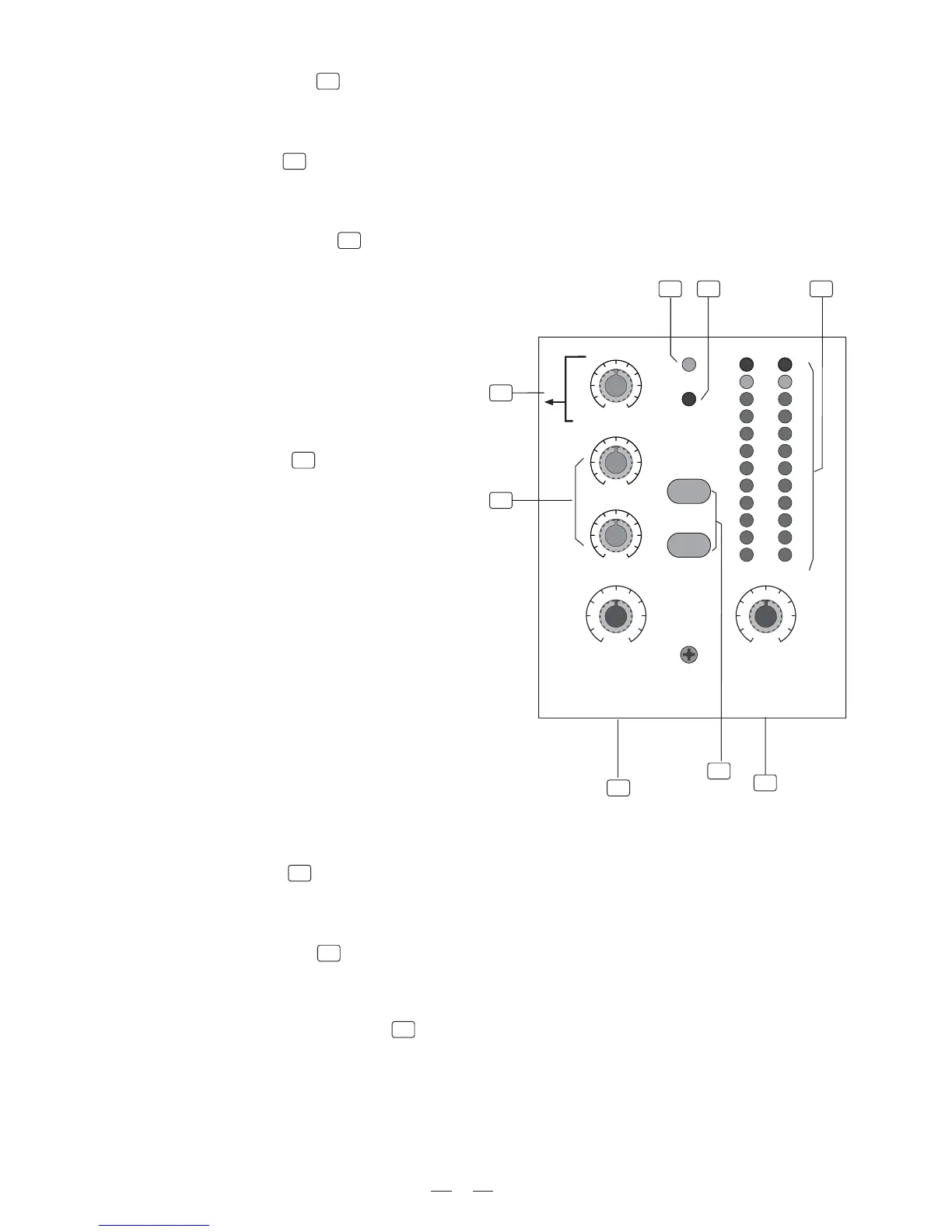
- POWER LED
This LED indicates when the Power is on in your PM-8 DRAGONFLY.
19
- PHANTOM LED
This LED indicates when the Phantom Power is switched on.
20
This Control sets the amount of signal sent to the Control Room and phone.
- PHONES/CONTROL ROOM
21
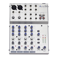
4.11 MASTER SECTION
15
- LED METER
This stereo 12 segments Led Meter will indicate the level of the overall output signal.
14
- MAIN MIX LEVEL
This Control sets the amount of signal sent either to the Main Out socket or to the Tape Output.
16
- 2 TRACK signal path
If you push down the 2TK TO CONTROL ROOM
button, the 2 TRACK IN signal will be routed
into the Control Room output and the level will
be adjusted by the Control Room knob nearby
the Main MIX LEVEL knob.
If you push the 2TK TO MIX button the 2 TRACK
IN signal will be routed into the MAIN output and will
be adjusted by the MAIN MIX LEVEL knob.
17
- AUX RETURN
As implied in the name, the Auxiliary Returns are
used to 'return' the signal from the external effects
or processors to the main mix, but, most of the
times, it can also be worked as the additional
stereo line inputs.
In this typical compact unit:
AUX RETURN1 is configured to be assigned to
the main mix bus permanently, for mono application,
only use the left input jack.
But for AUX RETURN2, instead of assigning the
returned signal to main mix bus, it can also to AUX1
bus, and in this case, adjust AUX2/DFX TO AUX1
knob (18) to control the input level.
Normally, AUX RETURN2 is connected rightly
with the output of the internal digital effects, but,
this signal flow will be broken, if you have any
external signal inserted from these two jacks.
11
 Loading...