1.0 SYSTEM DESCRIPTION
1.1
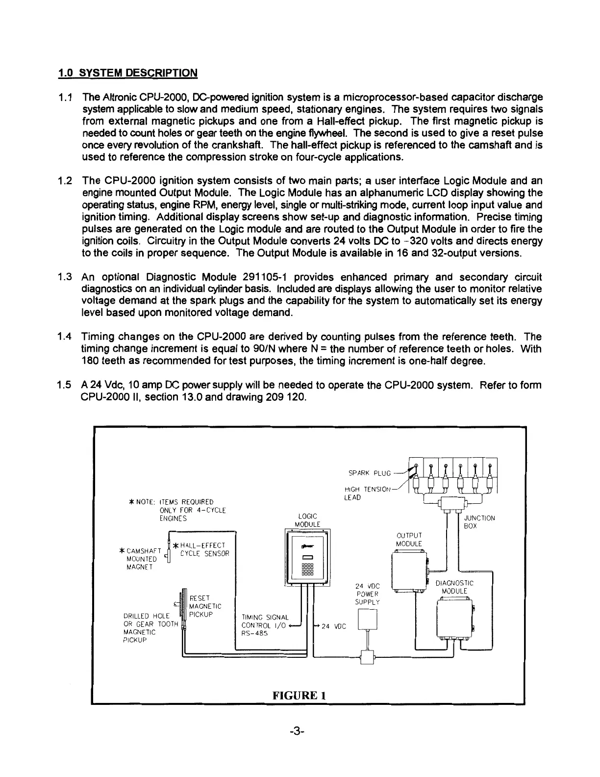
The Altronic CPU-2000, DC-powered ignition system is a microprocessor-based capacitor discharge
system applicable to slow and medium speed, stationary engines. The system requires two signals
from external magnetic pickups and one from a Hall-effect pickup. The first magnetic pickup is
needed to count holes or gear teeth
on
the engine flywheel. The second is used to give a reset pulse
once every revolution
of
the crankshaft. The hall-effect pickup is referenced to the camshaft and is
used to reference the compression stroke
on
four-cycle applications.
1.2 The CPU-2000 ignition system consists
of
two main parts; a user interface Logic Module and
an
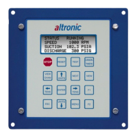
engine mounted Output Module. The Logic Module has an alphanumeric LCD display showing the
operating status, engine
RPM,
energy level, single or multi-striking mode, current loop input value and
ignition timing. Additional display screens show set-up and diagnostic information. Precise timing
pulses are generated
on
the Logic module and are routed to the Output Module in order to fire the
ignition coils. Circuitry in the Output Module converts 24 volts DC to
-320
volts and directs energy
to the coils in proper sequence. The Output Module is available in 16 and 32-output versions.
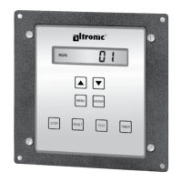
1.3 An optional Diagnostic Module 291105-1 provides enhanced primary and secondary circuit
diagnostics
on
an
individual cylinder basis. Included
are
displays allowing the user to monitor relative
voltage demand at the spark plugs and the capability for the system to automatically set its energy
level based upon monitored voltage demand.
1.4 Timing changes
on
the CPU-2000 are derived
by
counting pulses from the reference teeth. The
timing change increment is equal to 90/N where N
=
the number
of
reference teeth or holes. With
180 teeth as recommended for test purposes, the timing increment is one-half degree.
1.5 A
24
Vdc,
10
amp
DC
power supply will be needed to operate the CPU-2000 system. Refer to form
CPU-2000
II,
section 13.0 and drawing 209 120.
*
NOTE:
ITEMS
REQUIRED
ONLY
FOR
4-CYCLE
ENGINES
*
CAMSHAFT
MOUNTED
MAGNET
*
HALL-EFFECT
CYCLE
SENSOR
DRILLED
HOLE
OR
GEAR
TOOTH
MAGNETIC
PICKUP
RESET
MAGNETIC
PICKUP
TIMING
SIGNAL
CONTROL
1/0
RS-485
LOGIC
MODULE
-
=
□□□□
□□□□
□□□□
□□□□
SPARK
PLUG
HIGH
TENSION
-
LEAD
24
voe
24
voe
POWER
SUPPLY
OUTPUT
MODULE
=
FIGURE 1
-3-
JUNCTION
BOX
DIAGNOSTIC
MODULE