Do you have a question about the Altronic DE-3000+ Series and is the answer not in the manual?
Locating subjects via section index and glossary.
Details the controller's electronic, microprocessor-based design and capabilities.
Lists the four main components: MIDAS HMI, computer module, terminal module, and power supply.
Details the Ethernet, Serial, and USB ports available on the MIDAS HMI.
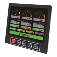
Describes the status strip, trends, bar graphs, and logging capabilities.
Explains the Modbus TCP/IP protocol used for HMI to computer module communication.
Describes the computer module's rail-mounting and connection to terminal/HMI.
Specifies the 10-32VDC, 0.2A max power requirement for the module.
Details the overview provided by the DE-3000+ Home page.
Explains how to configure the system's IP address and network settings.
Describes the serial port configuration and recommended settings.
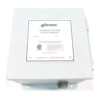
Explains the module's role and the use of industry-standard output modules.
Describes N/O, N/C operation and associated LED indicators.
Details usage of custom modules for fuel valve and ignition control.
Specifies power input terminals, fuse, and power LED.
Explains external connections for RS-485 communication ports.
Describes IGN IN and PU IN terminals for engine rotation detection.
Describes the terminal module's interface role and connections.
Lists compatible Altronic transducer series for inputs.
Details adding terminal boards to increase input capacity.
Details pressure transducer types, ranges, and connections.
Explains how to measure differential pressures or temperatures.
Details temperature transducer types, ranges, and connections.
Describes thermocouple input capabilities and compensation.
Explains wiring for normally-open and normally-closed sensor inputs.
Details the through-panel mounting instructions for the HMI.
Describes mounting the power supply module onto DIN rails or connecting it.
Details mounting the terminal module onto DIN rails or connecting it.
Provides guidance on mounting pressure transducers.
Describes wiring between system components like HMI, terminal, and power supply.
Explains how to connect power supply wires to the computer module and power supply.
Details the procedure for connecting the MIDAS HMI to earth ground.
Outlines the power supply requirements and considerations for the MIDAS HMI.
Provides detailed instructions for wiring discrete sensor inputs.
Lists requirements for installing the system in hazardous locations.
Describes the function of the HMI's bezel buttons for navigation.
Explains how to navigate through Main Menu and HMI Utility screens.
Details the process for logging into the MIDAS HMI.
Explains how to enable write control for modifying setpoints.
Details the two-step process for enabling and activating alarms.
Describes accessing screens via the Menu Popup at the bottom of HMI screens.
Explains using arrow keys to navigate between HMI screens.
Describes how to access the Home screen from the Main Menu.
Explains how to send a command to start the DE-3000+ controller.
Describes using the STOP key for a manual stop condition.
Explains how the HMI indicates unavailable menu functions.
Details the function of the TEST key for disabling outputs and testing sensors.
Explains the function of the CANCEL TIMERS key.
Describes the RESET key's function to clear faults and reset timers.
Explains how to initiate and cancel the cool-down timer.
Describes accessing the Linear Ramp popup for setting values.
Explains accessing the Lube Flow feature if configured.
Describes accessing and navigating Terminal Module screens.
Explains accessing and using Channel Status screens for monitoring.
Describes accessing the Process screen for monitoring and modifying setpoints.
Explains accessing the Driver screen for engine/motor related channels.
Details accessing and modifying PID values and setpoints.
Explains accessing and modifying Control SP values.
Explains accessing Class Timer screens for input class and time monitoring.
Explains accessing Raw Modbus Register screens for monitoring actual values.
Explains accessing trend screens for understanding channel behavior.
Details SD card capacity, status, formatting, and report generation.
Explains accessing the firmware date for CPU and terminal board.
Explains accessing system status for HMI battery and communication.
Explains how to configure the IP address for network communication.
Describes accessing and modifying the HMI's current time.
Explains accessing the Event screen for a log of controller events.
Explains accessing the Alarm Viewer for active and unaccepted alarms.
Details how to take and retrieve screenshots from the HMI.
Describes the procedure to manually start the engine using the RESET button.
Requirements for enabling and defining the AUTO START sequence.
Defines the initial engine stopped condition for AUTO START.
Describes the initial timed delay period in the AUTO START sequence.
Details the state where engine cranking begins after programmed delay.
Describes the first engine purge cycle without fuel or ignition.
Describes the second purge cycle with ignition but no fuel.
Details the state where fuel and ignition are enabled for engine start.
Describes the state after engine speed increases and starter is disabled.
Details the state for unloaded engine warmup before PID control.
Describes the state where PID output control begins based on configuration.
Explains how to configure the DE-3000+ for OEM Engine Control.
Describes the sequence of operation for OEM Engine Control.
Details the requirement for Pre-Lube disconnect before its time expires.
Specifies the RPM requirement for Crank/Multi-Start disconnect.
Describes the timing behavior of auxiliary and start/run signals.
Explains how signals behave upon manual stop or fault detection.
Offers general guidelines for selecting the most suitable control strategy.
Discusses controlling compressor throughput via capacity and engine speed.
Details using analog outputs for engine speed control via governors.
Explains analog and digital outputs for capacity control.
Basis for selecting primary control input based on site conditions.
Defines direct and inverse acting relationships for control inputs/outputs.
Details options for modifying secondary control setpoints.
Discusses applying PID control to analog outputs for processes.
Explains how cascade control enables engine speed control based on setpoints.
Describes mapping channel setpoints to 4-20mA states for control.
Provides an example of setting up linear/ramp control for suction pressure.
Describes the pulsed digital output control for solenoid/motor valves.
Explains how to enter test mode for sensor testing without output tripping.
Describes how high/low indications appear when testing analog channels.
Explains how to exit test mode using the CANCEL TIMERS button.
Explains how cool-down mode prevents faults on low sensors.
Describes the status indication when the cool-down timer expires.
Provides step-by-step instructions for calibrating transducers.
Explains the function of digital outputs configured as integrated timers.
Provides the URL to download the DE-3000+ PC terminal program.
Details Modbus RTU compliance and supported functions for the DE-3000+.
List of Modbus registers for status, inputs, and outputs.
Continued list of Modbus registers for inputs and outputs.
Continued list of Modbus registers for inputs and setpoints.
Continued list of Modbus registers for inputs and setpoints.
Continued list of Modbus registers for inputs and setpoints.
Continued list of Modbus registers for inputs and setpoints.
Continued list of Modbus registers for inputs and setpoints.
Continued list of Modbus registers for inputs and setpoints.
Continued list of Modbus registers for inputs and setpoints.
Continued list of Modbus registers for inputs and setpoints.
Continued list of Modbus registers for service meters.
Continued list of Modbus registers for service meter reset values.
Continued list of Modbus registers for service meter labels.
Continued list of Modbus registers for sensor limits and setpoints.
Continued list of Modbus registers for sensor limits and setpoints.
Continued list of Modbus registers for sensor limits and setpoints.
Continued list of Modbus registers for service meter hours remaining.
Continued list of Modbus registers for service meter reset values.
Continued list of Modbus registers for service meter resets.
Maps keypad inputs (KP) to their corresponding functions.
Notes regarding Modbus/Keypad and ASCII write counters.
Details on controlling analog outputs in auto/manual modes.
Notes explaining setpoint class and time associations.
Notes related to transducer calibration procedures.
Notes regarding hour/service meter readings and representation.
Definition of electromagnetic devices converting current to motion.
Definition of inputs accepting voltage signals (0-5V).
Definition of outputs providing 4-20mA current for control.
Definition of reducing gas volume moved per compressor cycle.
Definition of a full rotation of the compressor drive shaft.
Definition of programmed values for optimizing equipment function.
The RPM setting at which the starting device is de-energized.
Time after auto-start command before cranking begins.
| Brand | Altronic |
|---|---|
| Model | DE-3000+ Series |
| Category | Control Systems |
| Language | English |