Do you have a question about the Altronic DD-40NTV-O and is the answer not in the manual?
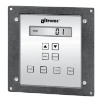
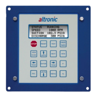
Describes the Altronic DD-40NTV digital annunciator as a 40-point monitor and shutdown device.
Lists the essential items included with the DD-40NTV annunciator for Class I, Division 2 use.
Details the availability of RS-232/RS-485 serial communications for remote engine monitoring.
Provides instructions for securely mounting the annunciator unit to a flat surface.
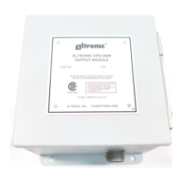
Details how to mount the 691200-3 Power Supply directly to the back of the annunciator.
Explains the connection between the annunciator unit and power supply via a DB-9 connector.
Describes connecting sensor leads to the removable terminal strips on the annunciator.
Offers guidance on stripping wires and securely tightening them in terminal strips.
Advises on wire condition, new wiring, and suitable termination methods.
Highlights critical sensor wiring rules, including separation from other wiring and insulation requirements.
Warns about checking sensors and potential issues from past exposure to high voltage.
Explains that the DD-40NTV unit must be configured before use, mentioning emulation modes.
Details the four selectable operating modes and how to program them.
Guides on setting the RPM pre-divide number, specifying signal sources and range.
Explains how to set the RPM overspeed value and disable the function.
Guides on setting the RPM underspeed value and disabling the function.
Details setting the time delay for the LUBE output actuation on start-up.
Explains setting the time delay for the LUBE output after a manual STOP or SHUTDOWN.
Describes setting the time delay for tripping SDI and OUTPUT 2 after a fault.
Guides on selecting the RUN state (N.O. or N.C.) for output SW1.
Guides on selecting the RUN state (N.O. or N.C.) for output SW2.
Explains how to select the type of serial communications (RS-232/RS-485, ASCII/Modbus).
Details selecting the baud rate for serial communications (9600 or 38.4k).
Guides on setting the unique node number for serial communication identification.
Explains how to set the pre-programmed number of operating hours.
Details selecting the type of power supply used (691200-1 or 691200-3).
Explains how to view and change Class B1 and B2 timer delays.
Lists the factory default settings for various parameters.
Explains how the MENU key allows viewing and changing various annunciator settings.
Describes using the UP ARROW key to increment selections or view data.
Describes using the DOWN ARROW key to decrement selections or view data.
Explains the ENTER key's role in saving selections and canceling lubrication.
Details how the STOP key initiates a shutdown condition.
Explains how the RESET key clears faults and resets timers/outputs.
Describes using the TEST key for battery, voltage, and sensor input tests.
Explains how the TIMER key allows viewing or modifying B1 and B2 delay timers.
Details the keypad sequence required to modify values, preventing unauthorized changes.
Explains the key combination to cancel active timers.
Introduces the operation section, referencing a chart for details.
Explains how to view RPM, hourmeter, and voltage readings using UP/DOWN keys.
Describes the annunciator's overspeed monitoring and its impact on fuel/ignition outputs.
Details the annunciator's underspeed monitoring and its impact on fuel/ignition outputs.
Provides information on the power supply's lithium battery life and replacement.
States the ratings for the two digital outputs, SW1 and SW2.
Explains that SW1 trips immediately upon a fault or STOP key press.
Describes SDI and SW2 tripping after a pre-programmed delay or STOP key press.
Lists voltage and current ratings for the 691200-1 and 691200-3 power supplies.
Specifies the LUB output is a solid-state device rated at 400 VDC, 0.5A max.
Details the conditions under which the LUB output remains actuated (RESET/STOP/FAULT).
Outlines the selectable communication protocols: RS-232 or RS-485 using ASCII or Modbus RTU.
Explains the RS-485 system's master/slave design where units respond to node addresses.
Describes the use of node numbers (1-99) to identify slave units in serial communication.
Details how ASCII characters are used for communication, simplifying debugging.
Lists key communication parameters: Baud Rate, Data Bits, Stop Bits, and Parity.
Explains the format and components of commands used in the annunciator's protocol.
Lists standard commands and their expected responses from the annunciator.
Details RS-485 communication setup including half duplex and electrical range.
Provides recommendations for RS-485 wiring, shielding, and wire gauge selection.
Provides guidelines for RS-232 communication, including wire length limits.
Details the Modbus RTU slave operation and lists the available registers and their values.
Summarizes key specifications and provides dimensional drawings for the DD-40NTV-O model.
Summarizes key specifications and provides dimensional drawings for the DD-40NTV-U model.
| Brand | Altronic |
|---|---|
| Model | DD-40NTV-O |
| Category | Control Systems |
| Language | English |