DE-3000+ IOI 8-15
All rights reserved © ALTRONIC, LLC 2015
5
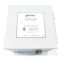
4.0 POWER SUPPLY MODULE
4.1 The Power Supply Module accepts up to four industry-standard, commercial-
ly-available 0.6 inch plug-in Output Modules. The Output Modules provide a
means of using the DE-3000+ Controller Safety Shutdown System status to
interface with other systems on the engine/motor and compressor. A typical
application would be as a relay or solenoid coil driver. The Output Modules are
optically isolated, solid-state switches which are isolated from power supply mi-
nus and engine ground. The Output Modules will be in the open (de-energized)
condition when the unit is not powered.
4.2 Outputs 1 and 2 can be software-configured for either normally-open (N/O) or
normally-closed (N/C) operation and have an LED indicator associated with them.
Outputs 3 and 4 are pre-programmed normally-open for use with the optional
OEM Engine Control or Auto start feature. If an Output Module is programmed for
normally-closed (energized for run), the LED will be ON in the normal run condi-
tion and OFF for a fault condition. For Normally-open configured modules the LED
will be OFF for normal run condition and turn ON for a fault condition.
4.3 The standard Output Module outputs use the top row of the dual 16-position
terminal strip which is marked OUT 1 through OUT 4. Each of these outputs
are fused with a replaceable 6.3 amp slow-blow fuse, Altronic P/N 601653.
In addition to accepting industry-standard Output Modules, a custom Altronic
Output Module P/N 691124 is available for tripping ignition powered CD fuel
valves and shorting CD ignition shutdown leads upon a fault. When making use
of OEM Engine Control, outputs 1 and 2 will not be wired to trip the fuel and ig-
nition valves. When both functions are required, two of these modules are used
as follows: OUT 1 slot must be used to trip the fuel valve, and OUT 2 slot must
be used to short the ignition. If 12-24Vdc is lost to the DE-3000+ annunciator
system, the custom Output Modules will trip the fuel valve and short the igni-
tion shutdown lead. This mimics the “fail-safe” operation of a normally-closed
Output Module and therefore the LED will be ON in the normal run condition
and OFF for a fault condition. In programming the system, these modules are
identified by using the IGN/FUEL selection. Terminals IGN+ and IGN− are used
to connect the shutdown lead, and FV1 and FV2 are used for the CD fuel valve.
A capacitor is included in the Power Supply Module to supply the energy to trip
the fuel valve.
4.4 The 12-24Vdc power for the DE-3000+ system is applied to the power supply
terminals marked (+) and (−) 12–24Vdc INPUT POWER. A 6.3 amp replaceable
slow-blow fuse protects the system from over-currents, and a power LED lights
when power is applied to the system.
4.5 The external connection for the two serial RS-485 communication ports is on
the Power Supply Module terminal strips. Port 2 is for RS-485 serial com-
munication to future Altronic instruments, and port 3 communicates internally
between two different boards within the computer module. Nothing should be
plugged into ports 2 and 3 for normal operations.
4.6 Terminals marked IGN IN and PU IN are used by the DE-3000+ system to de-
tect either engine rotation or ignition system firings. This input monitors chang-
ing signals such as those seen on either the ignition shutdown lead or a mag-
netic pickup monitoring an engine mounted gear.
THE MAGNETIC PICKUP INPUT MUST BE USED FOR APPLICATIONS EN-
ABLING THE AUTO START OR OEM ENGINE CONTROL FUNCTION.
• The IGN IN terminal connects to the positive (+) C.D. ignition shutdown lead.
• The PU IN terminal connects to one magnetic pickup input; the other pickup
wire connects to the minus (−) terminal on the Power Supply Module.
NOTE: AN INSTALLATION MAY USE ONLY
ONE OF THE TERMINALS IGN IN, PU IN,
OR T+.
 Loading...