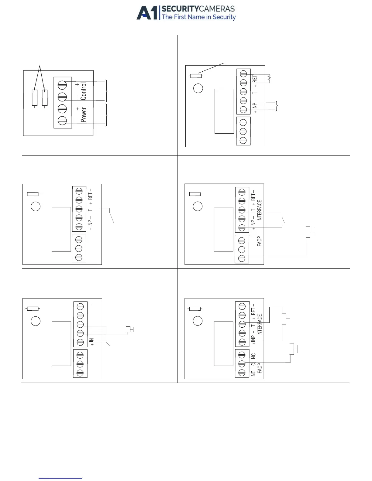
Hook-Up Diagrams:
Fig. 5 Normally Open - Non-Latching FACP
trigger input:
Fig. 6 Normally Open FACP Latching trigger input
with reset:
(This output has not been evaluated by UL)
Fig. 7 Normally Closed - Non-Latching FACP
trigger input:
Fig. 8 Normally Closed - Latching FACP trigger input
with reset:
(This output has not been evaluated by UL)
Fig. 4 Polarity reversal input from FACP signaling circuit
output (polarity is referenced in alarm condition):
Fig. 3 Optional hook-up using two (2) isolated
power supply inputs:
J2 J1
J1 AND J2
ISOLATED POWER INPUT
12 OR 24 VAC OR VDC
(LOCK POWER)
ISOLATED POWER INPUT
12 OR 24 VAC OR VDC
(ACM8 POWER)
JUMPER
FROM FACP
OUTPUT
CIRCUIT
+
--
FACP
OUTPUT EOL
TRG
NO C NC
FACP INTERFACE
JUMPER
N.C. DR
TRIGGER
INPUT
TRG
NO C NC
FACP INTERFACE
N.C. TRIGGER
INPUT
N.C. RESET
SWITCH
JUMPER
TRG
N.O. TRIGGER
INPUT
TRG
NO C NC
FACP INTERFACE
N.C. RESET
SWITCH
N.O.
TRIGGER
INPUT
JUMPER
TRG
NO C NC
- 8 - ACM series
Available from A1 Security Cameras
www.a1securitycameras.com email:sales@a1securitycameras.com
 Loading...