AL175UL Installation Guide - 3 -
Keep power-limited wiring separate from non power-limited wiring (115VAC / 60Hz Input, Battery
Wires). Minimum 0.25” spacing must be provided.
CAUTION: Do not touch exposed metal parts.
Shut branch circuit power before installing or servicing equipment.
There are no user serviceable parts inside. Refer installation and servicing to qualified service personnel.
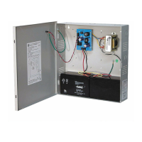
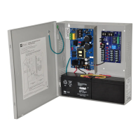
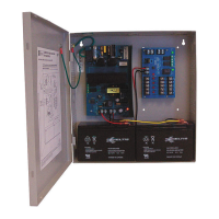
3. Set the AL175UL to the desired DC output voltage by setting switch SW1 to the appropriate position
(Power Supply Output Specification Table).
4. Measure output voltage before connecting devices. This helps avoiding potential damage.
5. Connect battery to the terminals marked [+ BAT –] (battery leads included).
Use two (2) 12VDC batteries connected in series for 24VDC operation.
Note: For Access Control applications batteries are optional.
When batteries are not used, a loss of AC will result in the loss of output voltage.
When the use of stand-by batteries are desired, they must be lead acid or gel type.
6. Connect appropriate signaling notification devices to AC Fail supervisory relay outputs marked [NC, NO, C].
Note: To meet UL requirements, AC Supervisory outputs must be connected to the zone of Alarm Control
Panel or to visual AC trouble indicator.
7. For Access Control Device & Fire Alarm Interface connections refer to desired Application Diagrams (pg. 6-7)
and Terminal Identification Chart (pg. 4).
Maintenance:
Unit should be tested at least once a year for the proper operation as follows:
Output Voltage Test: Under normal load conditions the DC output voltage should be checked for proper
voltage level (see Power Supply Output Specifications Chart).
Battery Test: Under normal load conditions check that the battery is fully charged, check specified
voltage both at the battery terminal and at the board terminals marked [+ BAT –] to
ensure that there is no break in the battery connection wires.
Note: Maximum charging current under discharges is 400mA.
Note: Expected battery life is 5 years; however, it is recommended changing batteries in
4 years or less if needed.

 Loading...